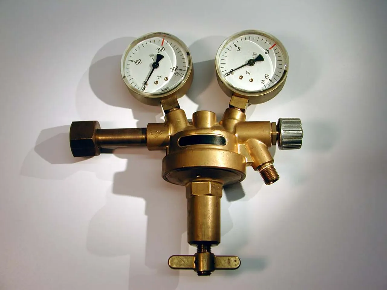
A back-pressure regulator is a self-operated control valve that senses the pressure upstream of itself and modulates to hold that upstream pressure at a set value, opening to relieve flow when the upstream pressure rises above setpoint and throttling closed as it falls. The sensing direction is the entire identity of the machine and the exact opposite of the pressure reducing valve, which senses downstream and protects the user from too much pressure; the back-pressure regulator senses upstream and protects the process from too little, maintaining pressure on a pump's discharge, a reactor's head, a separator, or a metering pump's output line so that the equipment upstream always works against the resistance it was designed for. It is a continuous-duty process control in a valve's body: no power, no instrument air, no controller, just a diaphragm or piston comparing upstream pressure against a spring or a dome load and moving a plug to keep the two in balance.
Specifying one is five linked decisions: the control problem itself, which upstream pressure must be held, against what disturbances, with what accuracy, and what flow must be relieved at the setpoint; the loading architecture, spring for simple adjustable duty, dome-loaded with a gas or pilot supply for precision and high capacity, pilot-operated for tight control at high pressure; the capacity and droop arithmetic, because every self-operated regulator's held pressure sags as relieved flow rises, the droop curve being the datasheet's honesty; the materials and trim against the fluid's chemistry, temperature, and, on gas service, the noise and erosion of the pressure letdown; and the boundary questions that keep the installation safe, the relief valve that guards the system regardless, and the failure position the process needs when the regulator's sense line or load fails. This page works each decision with catalog numbers and closes with the RFQ lines that make back-pressure regulator quotes comparable at engineering level.
This page treats the back-pressure regulator as upstream control made mechanical: sensing direction physics, spring and dome loading, droop and accuracy arithmetic, duty patterns from pump recycle to metering hold, the boundary against relief and reducing valves, and the RFQ lines that carry the specification.
Chapter 1 / 06
What a Back-Pressure Regulator Is and What Is Being Decided
The machine in one sentence: a plug, a seat, and an actuator whose load the upstream pressure fights. The upstream pressure, sensed internally through the inlet or externally through a sense line, acts on a diaphragm or piston; a spring or an external pressure load pushes the other way; when upstream pressure exceeds the load, the actuator moves the plug off the seat and relieves flow downstream; when it falls below, the plug throttles toward the seat. The equilibrium is continuous, the valve is always modulating slightly, and the upstream pressure is held in a band whose width the actuator's stiffness, the flow's disturbance, and the seat's gain decide. That band, not a point, is what a self-operated regulator delivers, and engineering it is the purchase.
What is being decided at purchase is which upstream pressure, how tightly, and how safely. First, the duty: pump discharge hold so a centrifugal pump never starves into shutoff or cavitation, process pressure sustain on a reactor, separator, or chromatography train, metering pump hold so the dosing line stays full and pressurized, compressed-gas header relief to a lower-pressure system, each with its setpoint, its relieved flow range, and its disturbance pattern, pump starts, batch steps, demand swings. Second, the architecture: spring-loaded, the simple adjustable workhorse; dome-loaded, an external gas or pilot pressure replacing the spring for higher precision, capacity, and remote setpoint; pilot-operated, a small pilot regulator driving the main actuator, the pattern for high pressures and large flows with tight bands. Third, the capacity arithmetic: the flow to be relieved at setpoint and at the maximum upset, read against the maker's curve with droop, the pressure band across that flow range, stated in the same breath. Fourth, the fluid contract: liquid or gas, chemistry, temperature, viscosity, and on gas the letdown ratio that brings noise and, at high ratios, erosion and icing. Fifth, the safety boundary: the back-pressure regulator is a control, never the last line, and the safety relief valve sized and certified for the system rides upstream or beside it, a line the hazard review writes and this page repeats.
The competitive frame keeps the selection honest, and most of it is a mirror. Against the pressure reducing valve, the physics is inverted and the duties do not overlap: the reducing valve senses downstream and gives a user or a low-pressure system a steady supply, the back-pressure regulator senses upstream and gives a source or a process a steady resistance; a plant needs both, on different sides of the pressure story, and confusing them in an RFQ buys the wrong valve installed backwards. Against the safety relief valve, the duty is continuous versus last-resort: the back-pressure regulator modulates all day and is not certified to protect anything, the relief valve sits closed for years and is certified to open at a set pressure and a capacity; the relief valve is mandatory regardless of how good the regulator is. Against a control valve with a pressure transmitter and controller, the self-operated machine wins on price and independence, no power, no air, no loop, and loses on accuracy, remote setpoint, and data, the closed loop holds a tighter band and reports what it held; the economics decide, and thousands of duties answer self-operated. Against a needle valve cracked open as a crude back pressure, the regulator wins everything except the purchase price, because the needle's resistance moves with every flow change and the regulator's does not.
One positioning note: this page is the single-product page for the upstream-sensing machine. The pressure reducing valve page carries the downstream story, the safety relief valve page carries the certified protection story, and the control valve page carries the powered loop; here the assumption is continuous upstream pressure control without external power, and every number that follows is chosen for that world.
Chapter 2 / 06
How Upstream Sensing Governs the Valve
The sensing direction writes the physics. The pressure that moves the actuator is taken from upstream of the seat, internally at the inlet port or externally through a sense line tapped a few diameters upstream, so the valve opens on rising upstream pressure: this is what makes it a back-pressure regulator, and installing it backwards, or piping the sense line downstream by mistake, converts it into a poorly tuned relief valve with no setpoint. The actuator is a diaphragm for the majority of duties, large area, low friction, sensitive at low and mid pressures, or a piston for high pressures where the diaphragm's strength runs out; the load is a spring, adjustable through a range by the setting screw, or a dome pressure, a regulated gas volume on the other side of the actuator, whose value is the setpoint and whose stability is the dome's volume and regulator quality. The equilibrium equation is simply load equals upstream pressure times effective area, and every architecture refinement, balanced plugs, rolling diaphragms, pilots, exists to keep that equation true as flow, temperature, and wear move around it.
Droop is the honesty curve. A spring-loaded regulator holding 5 bar at no relieve flow will hold less as the relieved flow rises, because the spring must compress further to open the plug, and the difference between setpoint at creep flow and held pressure at maximum flow is the droop, commonly a few percent to 15 percent of setpoint by design and spring range; the dome-loaded and pilot-operated architectures cut droop dramatically, to fractions of a percent on good designs, because the load does not move with plug travel. The specification consequence is direct: state the pressure band the process can tolerate across the full relieved-flow range and demand the droop curve or band statement in the quotation, because a regulator quoted only at setpoint and capacity, with no band across the range, is a lottery ticket. Accumulation and droop's cousin, the rise in held pressure at very low flows as the plug approaches its seat, bracket the band at both ends, and the maker's performance statement covers both when it covers anything.
Loading architecture
Typical band or droop
Setpoint mechanism
Duty where it wins
Spring-loaded diaphragm
several to 15 percent droop
Adjusting screw, range spring
General process hold, metering hold
Dome-loaded
fractions to a few percent
Dome gas pressure, remote settable
Precision hold, varying setpoints
Pilot-operated
tight bands at high pressure
Pilot regulator setting
High pressure, large flow, tight band
Piston actuated
by design, high pressure
Spring or dome on the piston
High pressure service windows
Stability is the dynamic half of the story. A regulator is a mechanical proportional controller and can hunt, oscillate around its setpoint, when the system's volumes and the valve's gain combine badly: long sense lines add lag, oversized seats give high gain at low travel, and the classic unstable installation is a big regulator barely open, chattering at a small disturbance. The engineering answers are sizing honesty, the regulator chosen so normal relieved flow sits in the middle of its curve, not the bottom; sense line discipline, short, generous bore, taken from a stable pressure point; and damping where the maker offers it, orifices in the sense path or actuator volumes that slow the loop to the process's rhythm. On gas service the letdown adds its own physics: high ratio pressure drops across the seat make noise, and where the ratio is several to one the low-noise trims and staged paths of the regulator catalog, or two regulators in series, each taking part of the letdown, are the engineering answers, the same physics the control valve world manages with its low-noise cages.
The failure positions complete the control picture, and the process chooses them. Spring-loaded back-pressure regulators fail toward closed as the load collapses, upstream pressure rising until the relief valve or the source limits it: an acceptable failure only where the hazard review says so. Dome-loaded units fail with their dome, a lost dome load closes the plug, a stuck dome load can hold it open; the dome supply is part of the safety argument and gets its own regulator and alarm. The sense line is the machine's truth: a blocked sense line blinds the valve into closing, a burst one vents the actuator and closes it too, on the standard architecture, so the sense line's routing, isolation, and mechanical protection are specification lines, not tubing details. None of this replaces the sentence from Chapter 1: the certified safety relief valve rides regardless, and the regulator's failures are business, the relief's are certified.
Chapter 3 / 06
Types, Construction, and Duty Boundaries
Construction follows the fluid and the pressure story. The general process regulators are globe-pattern bodies, bronze or steel or stainless by pressure class, with screwed or flanged ends from quarter-inch to six-inch and beyond, diaphragm actuators of fabric-reinforced elastomer or, for temperature and chemistry, metal, and trims of stainless with soft or metal seats. The gas services branch into the dome-loaded process regulators and the high-purity panel world, where small barstock and forged bodies, 316 and higher alloys, metal diaphragms, and bubble-tight soft seats serve analyzer trains, calibration gas headers, and semiconductor-adjacent duty; the panel regulator and its back-pressure cousin are the same machine scaled down and polished up. Liquids bring their own family: the metering-pump back-pressure valves, compact spring-loaded blocks sized for a few bar of hold at low flows, and the larger process sustain valves on pump discharges and skids. Materials ladder from brass and bronze through 316 stainless to Hastelloy and PFA-lined executions for the chemistry that eats the rest; elastomers, the diaphragm's fabric and the soft seats, are chosen against the fluid's list, and the temperature ceiling of the diaphragm, not the body, is usually the binding line.
The duty patterns name the applications the family lives on. Pump discharge hold: the regulator holds a minimum back pressure on a centrifugal pump's system, or rides a recycle line, so the pump stays off its shutoff head and its curve's unstable corner; the setpoint comes from the pump's curve and the system's hydraulics, and the relieved flow range is the recycle flow at minimum demand. Metering and dosing hold: the small back-pressure valve on a positive-displacement metering pump's discharge keeps several bar on the line so the check valves seat crisply, siphons cannot form, and the delivered dose stays linear; the classic sizing is a hold of roughly 2 to 5 bar with capacity for the pump's full stroke flow. Process pressure sustain: reactor overheads, separators, and header interfaces where the vessel must not see less than process pressure, the regulator venting to a lower-pressure consumer or flare. Gas letdown and relief to headers: dome-loaded regulators bleeding a compressor or bank of cylinders into a distribution header at a held upstream value. Test stands and injection: holding pressure on an injection pump or a test circuit so the measured element works against a real resistance. Each pattern sets the capacity range, the band tolerance, and the architecture choice, and the catalogs are organized around exactly these patterns.
Execution
Typical envelope
Duty where it wins
Hard boundary
Spring-loaded globe, process
0.3 to tens of bar, quarter to 6 inch
General upstream hold, skids
Droop on wide flow swings
Dome-loaded process
tight bands, remote setpoint
Precision sustain, varying duty
Dome supply dependency
Pilot-operated
high pressure, high flow
Header and letdown trains
Complexity, pilot maintenance
Metering pump hold valve
2 to 5 bar hold, low flow
Dosing and injection lines
Not a process control
High-purity panel type
small flow, tight band
Analyzer and calibration gas
Panel duty only
Low-noise or staged trims
by letdown ratio
High ratio gas relief
Price; capacity derate
Duty boundaries, sentence by sentence. Holding upstream pressure continuously, on liquid or gas, without power: the family owns the duty, architecture by band and flow as the table sets out. Protecting a system from overpressure: the safety relief valve owns it, certified, sized, and independent, and every regulator installation carries one. Supplying a steady reduced pressure to a user: the pressure reducing valve owns it, the mirror machine sensing the other side. Tight closed-loop control with remote setpoints and data: the control valve with a pressure transmitter and controller owns it, at a price the economics of each loop judge. Slam-open dump duty and fast safety venting: other machines. High-temperature service: metal diaphragm and metal-seat executions to their curves, and beyond them the powered loop. Slurries and solids-bearing liquids: soft-seat regulators suffer, and the honest answers are hardened trims or the powered loop with the right valve. The valve families around the installation complete the drawing: the isolation duty beside the regulator belongs to a ball valve or a globe valve by the line's habit, a gate valve or butterfly valve carrying the isolation on the larger lines, and the body materials ladder climbs from bronze through the stainless steel grades to the high alloys, while the certified relief stands apart from all of them. Upstream, the source that feeds the hold is often a diaphragm pump or a piston metering pump on dosing duty, and the pressure sensor behind the panel gauge reports the same band the regulator holds, so the loop's library reads consistently end to end. Every boundary is a sensing-direction, certification, or band statement, and Chapter 5 turns each into an RFQ line.
Chapter 4 / 06
Key Specification Parameters
The decode table is the datasheet skeleton. Every row is an RFQ line, and the two right columns are what each row decides and what it costs to leave blank.
Parameter
Typical catalog spread
What it decides
Setpoint range
0.3 to 400 bar family-wide by range spring or dome
The droop row is the one that separates control from optimism. State the process's tolerable upstream band across the full relieved-flow range and demand the regulator's band or droop statement at that range: the spring-loaded quote answers with a curve or a percentage, the dome and pilot quotes with tighter numbers, and the quote that answers only "setpoint 5 bar, Cv 4" has hidden the one number the control lives on. The setpoint row pairs with it: range springs come in overlapping bands, and a setpoint near a spring's top edge buys droop and stability problems that the next range down does not, so the RFQ states the setpoint and the band around it and lets the maker pick the spring.
The capacity row is the one that prevents the oversized mistake. A back-pressure regulator chosen for the maximum upset flow spends its normal life barely cracked open, high gain, hunting, and wearing its seat at the throttle point; chosen honestly for the normal relieved flow with the upset inside the curve, it sits mid-travel and stable. State normal and maximum relieved flow and the upstream pressures at both, and size to the maker's published flow curves, not the connection size. The letdown row prices the gas physics: state inlet and outlet pressures at maximum flow, and where the ratio is several to one, take the low-noise trim or staged option, or split the letdown across two regulators in series, because gas noise is bought at purchase or paid for in complaints.
The materials and seat rows carry the decade. The diaphragm is the temperature and chemistry ceiling, and its elastomer grade is a named line item; the soft seat that holds bubble-tight at rest is a wear item against high letdown and dirt, and the hardened or metal seat option prices its replacement cycle. The sense line row is small print with big consequences: internal sensing is simple and fine where the inlet is the process truth, external sensing with a short, protected line is the choice where the pressure to hold is a vessel or header rather than the valve's own inlet, and the isolation and routing of that line belong on the drawing. The certificate stack, materials to EN 10204, PED conformity by jurisdiction, Ex where the area reads it, closes the delivery ticket; a quote missing the stack is not cheaper, it is later.
Chapter 5 / 06
Selection Decision Factors and RFQ Language
The decision sequence runs from the process's pressure story outward, because every later step prices the earlier one.
Write the control objective as numbers: the upstream pressure to hold, the tolerable band across the relieved-flow range, the normal and upset flows with their upstream pressures, and the disturbances, pump starts, batch steps, demand swings, that will move the valve.
Choose the architecture on band and setpoint: spring for simple fixed holds and modest bands, dome for tight bands and remote or varying setpoints, pilot for high pressure and flow with control, piston where the pressure outgrows the diaphragm.
Size on the curve: normal relieved flow mid-curve, upset inside it, and the droop statement checked against the band the process tolerates; refuse the size that only fits the connection.
Fix the fluid contract: chemistry and temperature against body, diaphragm, and seat materials; gas letdown ratio against noise trims or staging; solids against hardened or metal seats or a different conclusion.
Engineer the installation: sense line internal or external and its routing and protection, the pressure gauge pair at inlet and outlet, isolation valves for removal, and the relief valve sized and certified regardless of anything else.
Decide the failure story with the hazard review: spring fail-closed on load loss, dome supply failure modes and its alarm, sense line failure consequences, and the relief valve's capacity covering the credible worst case.
Close with the commercial lines: setpoint and band delivered with the spring or dome settings stated, droop curve attached, seat and diaphragm kit part numbers and prices, certificates, and commissioning support for the setpoint proof.
The cost comparison is control economics against powered alternatives. A self-operated regulator with its gauges and relief valve prices a fraction of a control valve, pressure transmitter, controller, and air or power to run them, and for a fixed hold with a tolerable band it is the honest answer by margin; the powered loop earns its cost where the setpoint moves by recipe, where the band must be instrument-grade, or where the data must reach the historian. Within the self-operated family, the ladder is price-for-band: spring to dome to pilot, each step buying tightness and capacity, and the step is justified by the process's band tolerance, not by prestige. The metering-pump hold valve is its own small economy, priced as a commodity and failing as one when the dosing line's siphon costs a batch, the two-to-five-bar hold it maintains is the cheapest accuracy in the plant. Table the decision on cost per held-bar-year including the relief valve and the kits, and the boundary writes itself.
Duty
Configuration to specify
Watch line
Pump discharge hold and recycle
Spring or dome process regulator, mid-curve sized
pump curve setpoint basis
Metering pump dosing line
Compact hold valve, 2 to 5 bar
capacity at full stroke flow
Reactor or separator sustain
Dome-loaded, external sense line
band across batch flow range
Gas header relief and letdown
Pilot or dome, low-noise trim by ratio
noise and staging arithmetic
Analyzer and calibration gas
High-purity panel type, tight band
dead-volume and purity spec
Any installation
Certified relief valve beside it
sized and independent
The RFQ language that makes quotes comparable, written as the datasheet lines a vendor must answer with numbers: setpoint and its band across the stated flow range, the droop or band statement; architecture, actuator, and load mechanism; capacity at setpoint and at upset with the flow curve basis; sensing, internal or external, and the sense line provision; body, diaphragm, and seat materials named; seat tightness class; temperature window; letdown handling on gas; connections; failure position on load and sense loss; certificates; and the diaphragm and seat kit part numbers with prices. A quotation answering those lines is a control with a guarantee; anything else is a spring in a fitting.
Chapter 6 / 06
Installation, Standards, Failure Modes, and Maintenance
Installation follows the sensing truth. Pipe the valve in the flowing direction with the sense connection where the pressure to be held actually lives, internally at the inlet on the simple duties, externally with a short, generous sense line from the vessel or header on the others; protect the sense line, isolate it for service, and slope or loop it so liquid or condensate cannot blind it. Fit gauges both sides, the inlet gauge is the control's report card and the outlet gauge the letdown's; provide isolation valves and a bypass where removal must not stop the process; and give the valve the straight run its curve assumed, a few diameters of settled flow at the inlet, on the duties where the catalog asks. On gas letdowns, think about the neighbor's ears at purchase: the low-noise trim, the staged pair, or the insulation the complaint generates. And install the relief valve first, sized and set per the hazard review, because the regulator is a control and the relief is the promise.
The standards frame is the regulator world's own. Pressure equipment conformity rides the PED and its national siblings by jurisdiction and volume class; the performance statements, setpoint, band, droop, capacity, answer the maker's conformity and the industry's regulator test practice; gas service in classified areas invokes the Ex rules where electrical accessories ride along, dome solenoids, transducers; and the relief valve beside every installation carries its own certification regime, ASME or the local equivalent, which is the standard the safety argument actually leans on. The failure mode is a plant that bought the regulator as if it were the relief, or the relief as if it were the control, and the RFQ that names both machines with both duties is the standard's cheapest enforcement.
Failure modes arrive in a predictable order, and each has a specification answer. Droop discovered at commissioning, the held pressure sagging below the process's tolerance at full flow, shows a sizing or architecture miss: the answer is the band statement demanded at purchase and the architecture step when the band matters. Hunting on an oversized valve shows as pressure oscillation and seat wear: the answer is mid-curve sizing and the maker's damping orifice or actuator volume options. Diaphragm aging shows as slow setpoint drift and soft response, heat and chemistry doing their work: the answer is the elastomer honestly specified and the diaphragm kit on the midlife schedule. Seat erosion on high-ratio gas shows as rising leakage at rest and falling hold quality: the answer is the low-noise or staged trim bought at purchase or the letdown split across two valves. Sense line blockage shows as the valve closing against a blind pressure, the upstream gauge climbing: the answer is the sense line's routing, isolation, and the discipline of checking it at every service. Dome supply failure shows as the valve following the dome into closure or stalling open: the answer is the dome regulator's quality, its alarm, and the hazard review's acceptance of the direction. Frozen diaphragms in winter gas service show as sluggish control: the answer is dry gas, heat where the maker allows, and the winter walk.
Maintenance is a kit-and-calendar economy. Annually: setpoint verified against a reference gauge at two flows, creep and normal, the band recorded against commissioning; the seat tightness observed at rest, the gauges checked, the sense line proven; the dome supply regulator and its gauge audited. At midlife or by the drift record: the diaphragm and seat kit, an hour's bench work that returns the machine to its curve, priced at a fraction of replacement. The relief valve beside it follows its own certified schedule and is never skipped because the regulator "has been fine", the two sentences belong to different worlds. Keep one diaphragm kit per size and one dome regulator per fleet in stores for critical services; the rest is inventory theater.
The commissioning record closes the loop: as-built architecture and settings, setpoint proven at two flows with the band recorded, sense line routing drawn, relief valve setpoint and capacity filed beside it, failure positions traced and accepted by the hazard review, and the certificates against the tag. One page per installation, in the pressure file. Plants that keep it hold their pressures on evidence; plants that do not hold them on reputation, and reputation is not a band.
FAQ
What is the difference between a back-pressure regulator and a pressure reducing valve?
Sensing direction. The back-pressure regulator senses upstream and holds the pressure before it, opening to relieve when upstream rises: it protects a pump, reactor, or process from too little resistance. The pressure reducing valve senses downstream and holds the pressure after it, throttling to protect a user or low-pressure system from too much. A plant typically needs both, on opposite sides of the pressure story, and piping either one backwards buys the wrong control installed wrongly.
Can a back-pressure regulator replace a safety relief valve?
No, never. The regulator is a continuous-duty control with no certified overpressure function; the safety relief valve is a certified protection device that opens at a set pressure and capacity after everything else has failed. Every back-pressure regulator installation carries its own correctly sized and certified relief valve, and the hazard review owns both setpoints, the regulator's band and the relief's set, as separate decisions.
Why does my held pressure sag when flow rises?
Droop: a spring-loaded regulator must compress its spring further to open the plug for more flow, so the held pressure falls as relieved flow rises, commonly a few to 15 percent across the range by design. Demand the droop or band statement at purchase and check it against your tolerable band. Where droop is too wide, the dome-loaded or pilot-operated architectures cut it to fractions of a percent.
What hold pressure does a metering pump line need?
Typically 2 to 5 bar: enough to seat the pump's check valves crisply on every stroke, prevent siphon flow, and keep the dose linear against downstream variation, without stressing the fittings. The compact spring-loaded back-pressure valve is sized for the pump's full stroke flow at that hold, and the setpoint comes from the pump maker's recommendation rather than habit. Losing the hold costs dosing accuracy long before anything leaks.
Spring, dome, or pilot loading, which do I order?
Order the spring for fixed setpoints with tolerable droop, the simple and economical default. Order dome loading for tight bands, high capacity, or a setpoint that moves by recipe or signal, with the dome supply becoming part of the specification. Order pilot operation for high pressures and large flows that still need tight control. Each step up buys band and capacity at a price the process's tolerance justifies.
How do I stop my regulator from hunting?
Hunting is usually an oversized valve at low travel, high gain over a small disturbance. Size so normal relieved flow sits mid-curve, shorten and enlarge the sense line so it reports the process rather than its own lag, and take the maker's damping options, sense orifices, actuator volumes. On long gas lines the process volume itself sets the rhythm, and staging the letdown across two regulators often settles both the control and the noise.
What maintenance does it need?
A kit-and-calendar economy: verify the setpoint and band annually against a reference gauge at two flows, prove the sense line and the seat tightness at rest, and fit the diaphragm and seat kit at midlife or on the drift record, an hour on the bench. The dome supply's regulator and gauge get audited on the same visit. The certified relief valve beside it follows its own schedule and is never skipped because the regulator has been fine.