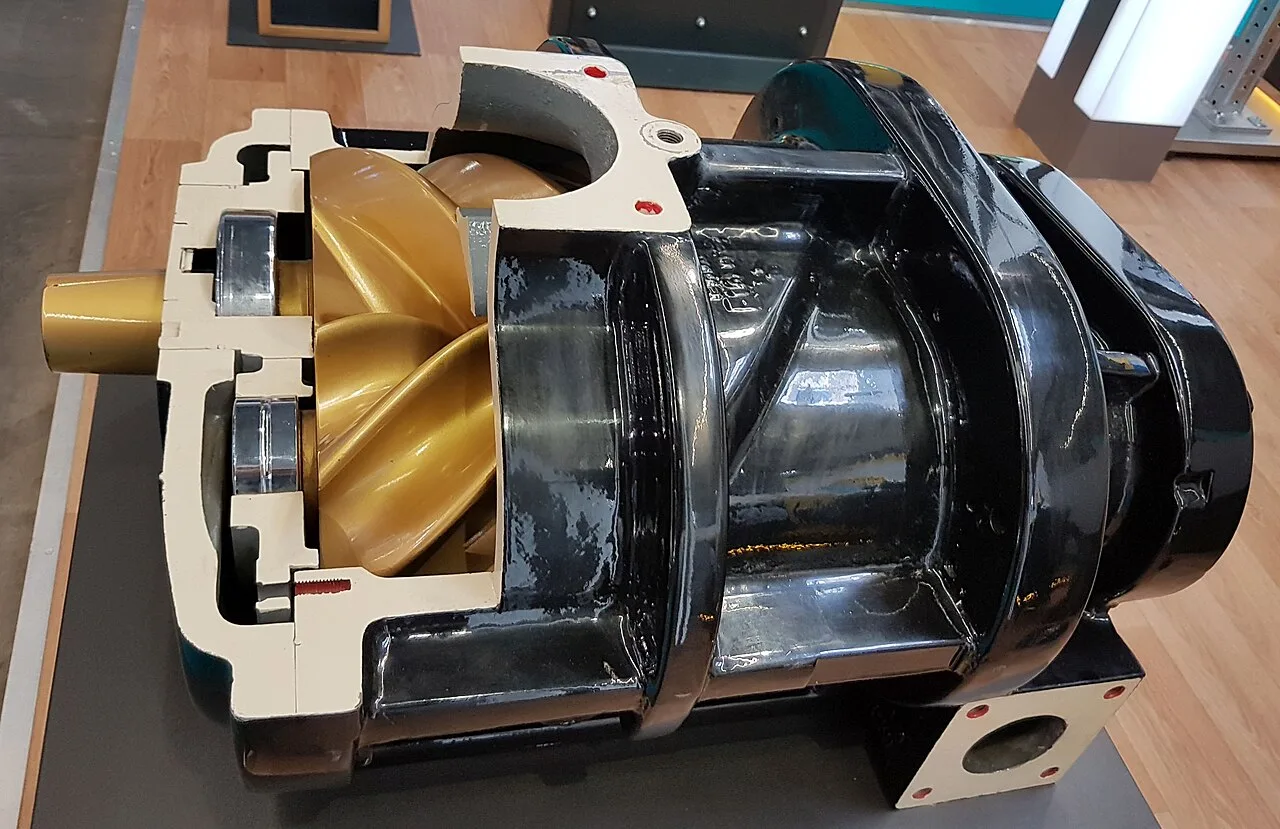
A screw compressor is a positive displacement rotary machine in which two helical rotors, a male lobed rotor and a female fluted rotor, mesh inside a casing to trap air at suction, reduce its volume along the rotor length, and discharge it at higher pressure. In the oil injected form that dominates industrial plant air, oil is sprayed into the casing where it seals the rotor clearances, lubricates the bearings and gears, and carries away the heat of compression in one circuit. There are no valves, no pistons, and no reciprocating masses, which is why the machine runs 20,000 to 40,000 hours between airend overhauls under competent care.
For a procurement engineer, the screw compressor is the default plant air decision: it is what almost every factory from 7.5 kW to 250 kW of installed air power actually buys. The decisions that land on the buyer are five: oil injected or oil free, fixed speed or variable speed drive, air cooled or water cooled, which control strategy matches the demand profile, and what air quality class the process actually requires downstream. This page works each decision with the numbers that matter: ISO 1217 capacity definitions, CAGI specific power data, ISO 8573-1 purity classes, and the failure modes that separate a 60,000 hour package from a 20,000 hour one.
This page decodes the screw compressor as a purchasing object: how the airend converts speed into pressure, what package specific power really measures under ISO 1217 and CAGI rules, how control strategy and air quality class drive both capital and energy cost, and how to write an RFQ that a supplier cannot answer with a brochure. It is written for engineers who buy compressed air by the kilowatt hour.
Chapter 1 / 06
What a Screw Compressor Is and What Is Being Decided
The screw compressor belongs to the positive displacement family, and the distinction matters immediately in a plant room. A reciprocating compressor raises pressure in batches, with valves and piston rings that wear and an inherent vibration signature. A centrifugal compressor raises pressure dynamically through an impeller, which makes it efficient at constant high flow but prone to surge when demand swings. The screw machine traps a fixed volume of air per rotor revolution and squeezes it continuously, so delivered flow is nearly independent of back pressure across its range: it keeps pumping 7, 8.5, or 13 bar with modest flow loss, which is exactly the behavior a fluctuating factory demand wants.
The core of the package is the airend: the rotor pair, their casing, and the bearings. Everything else in the cabinet exists to serve it. The electric motor drives the male rotor, which drives the female rotor through an oil film in the injected design or through timing gears in the oil free design. Oil injection is what makes the modern plant air package possible: by sealing the 20 to 100 micron clearances between rotors and casing, it lets a single stage reach 8 to 13 bar, which a dry screw could not do in one stage without multistaging. The same oil removes the heat of compression, keeping discharge air around 80 to 95 deg C, and it then passes through a separator, cooler, and filter train before being reinjected.
What is being decided at purchase time is therefore five commitments. First, oil injected or oil free: injected oil sets the floor of downstream purity at roughly 1 to 5 ppm carryover, which suits general plant air but not direct food, pharmaceutical, or instrument air contact without treatment, where oil free or Class 0 oil architectures apply. Second, fixed speed or variable speed drive: a VFD package matches flow to demand and saves 15 to 35 percent of energy on swinging loads, but costs more up front and does not pay back on flat loads. Third, cooling: air cooled packages reject heat into the room, water cooled into a utility loop that usually moves its water with a small centrifugal pump. Fourth, control strategy against the demand profile. Fifth, the downstream purity train, dryers and filters, specified as an ISO 8573-1 class per the process, not as a bundle.
The boundary against neighbors is worth fixing early. The same rotor geometry runs in reverse as a dry screw vacuum pump on process vacuum duty, and buyers meet that machine in the vacuum world; this page stays with pressure service. Below roughly 5 kW, scroll and small reciprocating packages are cheaper and quieter. Above roughly 250 kW of air power or 40 m3/min at constant demand, centrifugal machines win on specific power at the design point. Between those bounds, for swinging demand between 30 and 100 percent of capacity, the oil injected screw compressor is the dominant answer for good reasons, and the rest of this page is about buying it well.
Chapter 2 / 06
How the Airend Compresses Air
The rotor pair is the heart. The common industrial profile is a 4 plus 6 arrangement, four male lobes meshing with six female flutes; 5 plus 6 profiles appear in newer designs seeking different flow and efficiency tradeoffs. As the male rotor turns, typically 1,500 to 6,000 rpm depending on frame size, an interlobe volume opens to the suction port, fills with air at inlet density, closes, and shrinks along the axis as the meshing line travels toward the discharge end. The internal volume ratio of the airend fixes how far the trapped air is squeezed before the discharge port opens; when the built in ratio does not match the system pressure the machine runs over or under compressed, and the mismatch shows up as specific power loss, typically a few percent per bar of mismatch.
Oil injection happens at the compression phase. Injected oil, typically at 60 to 90 deg C arriving from the separator circuit, does three jobs at once: it seals rotor to rotor and rotor to casing clearances, it absorbs the heat of compression so the process stays close to isothermal rather than adiabatic, and it lubricates the bearings and, in most designs, the female rotor drive contact. Without oil, the same geometry would need tighter clearances, timing gears, and multiple stages to reach plant air pressures, which is exactly what an oil free screw package contains and what it costs.
The air-oil mixture leaves the airend at 80 to 95 deg C and passes into the separator vessel, where most oil falls out by velocity change and the remainder is caught in a coalescing element down to the 1 to 5 ppm carryover that a healthy package delivers. The separated oil flows through a thermostatic valve: cold oil bypasses the cooler to warm up quickly, hot oil passes through the cooler before reinjection. Discharge air then passes the aftercooler and, depending on the package, a minimum check arrangement that prevents the receiver from blowing back through the airend at shutdown. The air receiver and downstream dryer finish the train. Every one of these components appears on the CAGI data sheet, which is why chapter 4 leans on it.
Capacity definitions are where quotations go wrong, and ISO 1217 is the reference that fixes them. Actual volume flow, free air delivery, is the volume the machine would occupy at stated inlet conditions; displacement is the geometric swept volume and is always larger. A quotation that states displacement where a competitor states free air delivery overstates capacity by 10 to 25 percent. Package specific power, the number that decides a decade of electricity bills, is package input power divided by free air delivery, expressed in kW per m3/min; class leading oil injected packages sit near 5.5 to 6.0 and the general market runs to about 7.0, with US sheets quoting the equivalent 18.5 to 24 kW per 100 cfm. These numbers include fan and oil pump power because they are measured at the package boundary under ISO 1217 acceptance conditions.
Control behavior explains the energy story. When system pressure reaches the unload set point, the inlet valve closes and the machine blows down its separator to the sump, then runs unloaded consuming 20 to 30 percent of full load power while making no air. When pressure falls to the load point, it reloads. This load and unload cycling is efficient only when the unloaded periods are short; a machine spending half its life unloaded is spending 10 to 15 percent of full load power on nothing. A pressure switch or an internal pressure sensor performs the state change on simple packages, and a VFD package replaces the whole cycle by modulating speed against a target pressure, which is why its energy advantage is largest exactly where demand swings hardest.
Motor starting is the electrical boundary condition. Across the line starting stresses the supply; star delta reduces inrush at the cost of transition transients; a soft starter ramps the voltage and is the common choice on 30 to 90 kW frames; a VFD starts the machine at essentially zero inrush and at reduced speed, which also removes the unloaded start waste. Start frequency matters as much as method: each start warms the motor and loads the airend bearings, and most manufacturers cap starts per hour, which is one input the control strategy in chapter 5 must respect.
Chapter 3 / 06
Types, Construction, and Duty Boundaries
Oil injected packages are the volume product in four variants: fixed speed, variable speed, air cooled, and water cooled. The fixed speed machine with load and unload control is the cheapest per kW and suits steady demands. The VSD machine carries an integrated drive and a motor winding specified for the inverter duty, sacrifices a few percent at full load to converter losses, and wins the money back on swinging loads. Air cooled packages move their heat into the room through an axial fan, which is free cooling infrastructure but a real HVAC load; water cooled packages reject through a shell and tube or plate exchanger into a loop the plant already owns, and they fit noise and heat constrained rooms better at large sizes.
Oil free screw packages, dry screw with timing gears or water injected, exist for processes that cannot accept oil aerosol: food and beverage air in direct product contact, pharmaceutical air to ISO 8573-1 Class 0, instrument air for certain analyzers, and gas duty where hydrocarbon carryover is unacceptable. The dry screw airend keeps oil completely off the gas path; its rotors run on timing gears with no contact, its shafts are sealed against the bearing circuit with a mechanical seal or labyrinth and ring arrangement, and its casing jackets carry cooling water or oil. Two stages reach 7 to 10 bar typical. The price of purity is capital: an oil free package runs roughly 1.5 to 2.5 times the injected price per kW, and downstream stainless steel piping on the clean air side is normal where corrosion would contaminate the air the machine just cleaned.
Package construction follows duty class. Industrial duty packages run belt or direct drive at 2,900 rpm class motors with rolling element airend bearings. Heavy duty and machinery industry packages, the class the major makers sell into 24 hour process plants, carry oversized airends running slower, heavier oil systems, and separation filtration rated for continuous load; the slower turning airend is quieter and lives longer at the cost of package size. Marine and harsh environment variants add coatings, heaters, and larger separators. The dry screw vacuum pump cousin appears again here as the mirror image: same rotor family, no oil in the gas path, running to a vacuum target instead of a pressure one.
Duty boundaries close the map. A screw compressor does not tolerate liquid slugs of water or process fluid into the airend; intake siting and drainage protect it. It does not like continuous operation below roughly 20 percent load, where oil temperatures fall, water condenses inside the oil circuit, and the separator element loads with condensate. It is not a pressure vessel: the separator, receiver, and aftercooler are governed pressure equipment and carry their own relief and inspection regime. And it is not a silent machine: 62 to 85 dB(A) package ratings are normal, and enclosure quality is a purchase line, not a freebie.
The table below fixes the type boundaries into one screen a specifier can compare against a quotation.
Type
Pressure range
Package specific power, kW per m3/min
Downstream oil class
Best duty
Oil injected, fixed speed
7 to 13 bar
5.7 to 7.0
ISO 8573-1 Class 2 to 4 with treatment
Steady 60 to 100 percent demand
Oil injected, VSD
7 to 13 bar
5.5 to 6.5 across 30 to 100 percent speed
Class 2 to 4 with treatment
Swinging demand, 15 to 35 percent energy saving
Water injected screw
7 to 10 bar
5.8 to 6.8
Class 0 or 1 oil achievable
Oil sensitive duty at mid pressure
Dry screw, oil free, two stage
7 to 10 bar
6.5 to 8.0
Class 0 oil by design
Food, pharma, instrument air, gas duty
Reciprocating piston
7 to 30 bar and above
6.0 to 8.5 small frames
Depends on lubrication
High pressure, low flow, intermittent
Centrifugal dynamic
7 to 10 bar
5.0 to 6.0 at design point
Class 0 oil by design
Constant large flows above 40 m3/min
Chapter 4 / 06
Key Specification Parameters
The rows that decide whether a quoted package matches the service are consolidated below. Two conventions make the table usable: capacity is free air delivery at ISO 1217 package boundary conditions, and specific power is package input power divided by that flow, so motor, fan, and losses are included. A datasheet that does not state both is not a datasheet.
Attribute
Typical range or options
What it decides
Package power
7.5 to 250 kW motor frames
Air output class, electrical supply, starter architecture
Free air delivery
1.0 to 40 m3/min at stated pressure
Whether the machine covers demand; compare only at equal pressure
Set pressure
7 to 13 bar, single stage injected; 7 to 10 bar oil free
Every 1 bar of unnecessary pressure costs roughly 6 to 8 percent energy
Package specific power
5.5 to 7.0 kW per m3/min, CAGI verified
Decade of electricity; the single most important economic row
Airend profile and speed
4+6 or 5+6 rotors, 1,500 to 6,000 rpm
Efficiency, noise, and overhaul life expectations
Oil carryover
1 to 5 ppm after coalescing
Downstream filter load and ISO 8573-1 oil class feasibility
Load and unload, modulation, VSD; pressure switch, pressure sensor, or pressure transmitter per package
Energy behavior on the real demand profile and remote monitoring path
The measurement frame behind those rows is ISO 1217, the acceptance test standard for displacement compressors, and the CAGI data sheet program that publishes comparable package data under it. CAGI sheets state free air delivery, package power, and specific power at stated conditions, and the performance verification program audits participants' published numbers, which is the closest thing this market has to an independent referee. Buyers comparing two quotations should lay the CAGI sheets side by side at the same pressure; the specific power spread between an efficient and an average 90 kW package, roughly 0.8 kW per m3/min, is worth several thousand US dollars per year at typical utilization.
Air purity is specified, not assumed, and ISO 8573-1 is the class language. The standard defines three contaminant axes, particles, water as pressure dew point, and oil, each with classes 0 to X where 0 means "as specified by the buyer" and higher numbers are looser. A refrigerated dryer holds about 3 deg C dew point, Class 4; a desiccant dryer reaches minus 40 or minus 70 deg C, Class 2 or 1. Oil classes run from 0.01 mg per m3, Class 1, up to 5 mg per m3, Class 5; a healthy injected package with coalescing filtration delivers Class 1 to 2 oil, while oil free designs exist precisely to guarantee Class 0. The RFQ states the required class triplet, and the point of use train, typically an FRL unit for regulation, filtration, and lubrication at the tool, is matched to it.
The technology comparison table closes the parameter chapter; it is the honest answer to "why a screw" and belongs in every specification file.
Technology
Flow range
Pressure reach
Duty character
Maintenance posture
Oil injected screw
1 to 40 m3/min
7 to 13 bar
Continuous, load tolerant, flow nearly flat with pressure
Oil and filters on intervals; airend overhaul 20,000 to 40,000 h
Reciprocating piston
0.1 to 10 m3/min
To 30 bar and beyond
Intermittent, high pressure, low flow
Valves and rings wear; vibration and drainage checks
Centrifugal
30 to 300 m3/min
7 to 10 bar
Constant flow, surge limited at turndown
Low wear but sensitive to dirt and surge events
Scroll
0.05 to 1 m3/min
7 to 10 bar
Quiet, oil free options, small frames
Seal and scroll replacement; lab and dental duty
Dry screw vacuum variant
Pumping speed by model
To rough and medium vacuum
Process vacuum, oil free gas path
Timing gears and seals monitored closely
Chapter 5 / 06
Selection Decision Factors and RFQ Language
The selection sequence runs as a checklist; each step eliminates a class of quotation before price comparison begins.
Measure the demand profile: minimum, average, and peak flow, the pressure the tightest user actually needs, and the swing pattern across shifts.
Fix the set pressure at the real requirement plus line losses; every unnecessary bar costs 6 to 8 percent of energy.
Choose oil injected or oil free from the process exposure, then specify the ISO 8573-1 class triplet and the dryer type that delivers the dew point class.
Match control strategy to the profile: load and unload for steady loads, start and stop for small intermittent loads, modulation with care, VSD for swinging loads.
Compare offers on CAGI specific power at equal pressure, not on motor size or displacement.
Set the electrical interface: supply capacity against inrush, soft starter or star delta on fixed speed, VFD harmonics review where the drive route is taken.
Plan the room: heat rejection, ventilation, intake air quality away from dust and exhausts, condensate drainage and treatment.
Decide multi unit strategy: base plus trim, sequencing through a master controller or PLC, and N plus one redundancy for critical plants.
Control strategy against demand profile is the decision that dominates energy cost, and the table below is the short version of it. Load and unload wastes 20 to 30 percent input power during unloaded periods; modulation, throttling the inlet, avoids blowdown losses but slides efficiency at part load; start and stop suits only small machines with long idle periods because starts stress motor and airend; VSD tracks demand continuously between roughly 20 and 100 percent speed. On a two shift plant whose nights draw 25 percent of day flow, the VSD premium pays back in one to three years; on a flat 90 percent load, it never does, and the honest quotation says so.
Control strategy
Best demand shape
Part load behavior
Watch items
Load and unload
Steady 60 to 100 percent
Unload consumes 20 to 30 percent power
Receiver sizing; blowdown tuning; start limits per hour
Modulation inlet
Moderate swings near full load
Efficiency falls steeply below 70 percent flow
Not efficient deep into turndown; combine with unload
Start and stop
Small machines, long idle gaps
Zero idle power between runs
Motor start stress; minimum run and stop times
VSD modulation
Swinging 20 to 100 percent
15 to 35 percent energy saving on variable profiles
Premium efficiency at full load slightly lower; harmonics
Multi unit sequencing
Plants with 2 to 8 machines
Trim machine absorbs the swing
Sequencing controller or PLC logic; communication to BMS
Downstream pairing follows from the purity class. The dryer choice sets the dew point class: refrigerated for 3 deg C where indoor lines stay warm, desiccant for minus 40 or minus 70 deg C where lines see cold or the process is moisture sensitive. Point of use treatment finishes the train: coalescing and particulate filters before the FRL unit that regulates and, where tools need it, lubricates; oil free lines skip the lubricating leg and often specify stainless steel or coated piping so the Class 0 air stays Class 0 at the point of use. Condensate from dryers and separators carries oil and must route to a separator drain, not the storm system; it is the line item most often forgotten in the layout and most expensive to retrofit.
Protection and monitoring close the machine scope. The separator and receiver side carry a safety relief valve each, tested on the pressure equipment schedule, and the airend has thermal protection against oil loss. Monitoring spans the ladder from a mechanical pressure switch driving load and unload, through a package pressure sensor with local display and alarms, to a pressure transmitter feeding a plant PLC or BMS for trending and sequencing; most buyers now specify at least the transmitter route on machines above 45 kW, because the data pays for itself in the first leak survey.
The RFQ block should be written once and reused. A complete block reads: required free air delivery at set pressure with demand profile and diversity; ISO 8573-1 class triplet required at each critical point of use; package type, oil injected or oil free, and cooling mode; control strategy and whether VSD is offered as an alternative with its CAGI sheet; motor power, efficiency class, and starter type, star delta, soft starter, or drive, with supply fault level constraints; CAGI data sheet and ISO 1217 acceptance test requirement; noise, dimensions, and heat rejection figures; dryer, filters, receiver, and condensate treatment scope; monitoring level, local controller or PLC integration; and documentation: performance test report, wiring schematics, maintenance schedule, and warranty terms on airend and package. A quotation returned without a CAGI sheet or an equivalent ISO 1217 data set at the stated pressure is not comparable, and a supplier who quotes motor size where capacity was asked has not answered the question.
Chapter 6 / 06
Installation, Standards, Failure Modes, and Maintenance
Installation sets the operating envelope. The intake is the machine's lung: it must draw clean, cool air away from compressor room heat, dust, and any solvent or exhaust source, through a filter the schedule actually maintains; every 10 deg C of intake warming costs about 3 percent of output. The room must reject the package heat, tens of kW on mid frames, or the machine eats its own exhaust. Water cooled packages tie into the plant loop through isolating valves and a Y strainer on the inlet, with the loop moved by the plant's centrifugal pump or cooling utility; flow and quality limits in the datasheet are contract terms, not advice. Foundations or inertia blocks carry the vibration; the discharge line runs to the receiver through the aftercooler and dryer with slopes and drains so condensate never pools toward the machine.
Commissioning proves the train in order: verify rotation, run unloaded, check oil level and cooler function, then load and record the actual specific power from the meter against the CAGI sheet. Record discharge temperature, oil temperature, and unloaded blowdown time as baseline data; every future fault diagnosis leans on these four numbers. Configure the pressure switch or controller bands, verify the safety relief valve leads and seal, and confirm condensate drains actually drain under load, because a dryers drain that fails silently puts water into the distribution within a day.
The standards frame is compact. ISO 1217 governs the acceptance test that stands behind every credible capacity and power claim. The CAGI data sheet program and its performance verification scheme make those claims comparable between makers. ISO 8573-1 defines the air purity classes the RFQ uses. Pressure equipment directives and local codes govern the receiver, separator, and relief arrangements, and the machine's electrical package meets the usual low voltage and EMC regimes, with the VFD route adding harmonics requirements that the plant electrical engineer signs off. None of this is optional literature; it is the acceptance basis of the purchase.
Failure modes follow a predictable short list. Oil aging: oxidation raises acidity and deposits varnish on coolers and separators; mineral oils change near 2,000 to 4,000 hours and synthetics reach 4,000 to 8,000, sample guided intervals beat calendar guessing. Water in oil: condensation from long low load running emulsifies the charge; the fix is a minimum load policy and a thermostatic valve that holds oil above 70 deg C. Separator loading: a rising pressure drop across the coalescing element past roughly 0.8 to 1.0 bar says replace it, and ignoring it lifts oil carryover into the plant. Intake filter neglect: a starved inlet costs capacity and overheats the airend. Bearing wear: vibration rising at shaft and bearing frequencies over quarters is the precursor; on oil free machines the timing gears and shaft mechanical seal are watched the same way. Minimum duty cycle: short cycling floods separators and fatigues motors, which is why controller start limits are protection, not inconvenience.
Maintenance intervals scale with running hours and environment. Daily: hours, load state, oil temperature, and drain function walk past. Weekly: intake filter condition, belt or coupling inspection, leaks heard at the headers, and condensate separator level. Every 2,000 to 8,000 hours by oil type and analysis: oil change, oil filter, air filter, and separator element on condition. Annually: cooler cleaning on air cooled machines, where a clogged cooler is the top cause of summer trips, and on water cooled machines the cooler service plus cleaning the cooling water Y strainer; electrical checks on contactors and, on fixed speed machines, inspection of the star delta or soft starter; calibration of the pressure sensor or pressure transmitter against a reference gauge; verification of each safety relief valve; and retrieval of trend data from the controller or PLC for a yearly energy check of specific power against commissioning baseline. Airend overhaul at 20,000 to 40,000 hours is a planning event with a quoted exchange price in the contract, not an emergency. Every line here is cheaper than a stoppage on a two shift plant, and the trend data is what converts maintenance from calendar guessing into engineering.
FAQ
Should I buy an oil injected or an oil free screw compressor?
Buy oil injected unless a process cannot tolerate oil aerosol in direct contact. Injected packages deliver 1 to 5 ppm carryover, which coalescing filtration reduces to ISO 8573-1 Class 1 or 2 oil, adequate for most plant air. Food, pharmaceutical, and sensitive instrument duties justify oil free or water injected designs at 1.5 to 2.5 times the price per kW, specified to Class 0. State the required class triplet in the RFQ and let both architectures quote against it.
Is a variable speed drive package worth the premium?
On swinging demand between roughly 20 and 100 percent of capacity, yes: manufacturers and field data agree on 15 to 35 percent energy savings, and a two shift plant with light nights typically pays back the premium in one to three years. On flat loads above 80 percent, no: the drive adds converter losses, harmonics review, and capital without hours to recover them. Quote both options with CAGI sheets and compare on your measured profile, not on the brochure curve.
How do I read a CAGI or ISO 1217 data sheet?
Check three rows at your set pressure: free air delivery, package input power, and package specific power in kW per m3/min. Confirm the sheet states ISO 1217 package boundary conditions so motor and fan losses are included, and that capacity is free air delivery, not displacement, which overstates flow by 10 to 25 percent. Class leading injected packages sit near 5.5 to 6.0 kW per m3/min; 0.8 difference on a 90 kW machine is real money every year.
Why is oil carryover rising in my plant air?
Check the separator element first: pressure drop across the coalescer above roughly 0.8 to 1.0 bar means the element is loaded and oil passes downstream. Second, verify oil temperature and level, because overheated oil atomizes finer and separates worse. Third, look for long low load runs that flood the separator with condensate. Fix the element, hold minimum load policy, and confirm the downstream coalescing filters match the ISO 8573-1 class you specified.
What pressure should the compressor be set to?
The lowest pressure the most demanding user actually needs, plus line and filter losses, typically 6 to 8 bar in a general plant. Every 1 bar of avoidable pressure costs roughly 6 to 8 percent of the machine's energy, and it also raises leak losses. Survey the real point of use requirements before setting the band, then size the receiver and control bands so the machine is not cycling to hold pressure nobody uses.
What dew point do I need, and which dryer delivers it?
A refrigerated dryer holds about 3 deg C pressure dew point, ISO 8573-1 Class 4, which suits indoor plants with warm lines. Desiccant dryers deliver minus 40 or minus 70 deg C, Class 2 or 1, for outdoor lines, cold rooms, instrumentation, and moisture sensitive process air. Specify the class in the RFQ rather than a dryer type, and let suppliers offer the energy efficient match, remembering desiccant units consume purge air that counts against capacity.
What maintenance schedule does a screw package need?
Daily walk checks of load state and drains, weekly filter and leak checks, oil and filter changes every 2,000 to 8,000 hours guided by analysis, separator element on condition at roughly 0.8 to 1.0 bar pressure drop, annual cooler cleaning, electrical inspection, instrument calibration, and relief valve verification. Plan the airend overhaul as a quoted exchange at 20,000 to 40,000 hours. Trend specific power from the controller against commissioning data to catch degradation early.