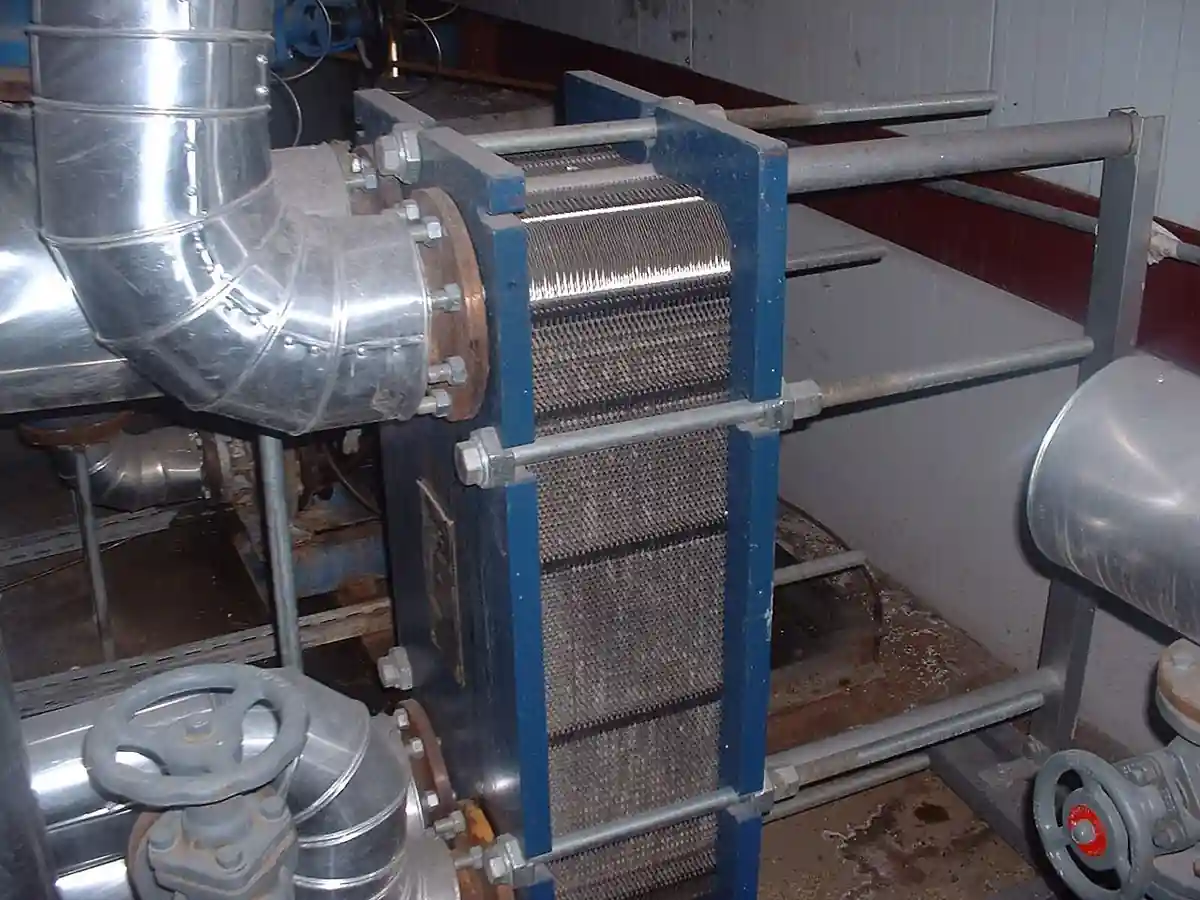
A shell and tube heat exchanger is a pressure vessel in which one fluid flows inside a bundle of parallel tubes and another fluid flows across and along the bundle inside a cylindrical shell. Tube-side fluid enters through a channel head, traverses one or more passes, and leaves; shell-side fluid enters a nozzle, is steered by baffles across the tube field in a zigzag path, and leaves through the outlet nozzle. The design is the default thermal machine of process industry: it holds from vacuum to hundreds of bar, from cryogenic to 600 deg C and beyond, cleans, re-tubes, and re-rates, and nearly every other exchanger type is chosen by arguing against it.
Specifying one means deciding three linked things: the TEMA construction type, which fixes how the bundle handles thermal expansion and how it is serviced; the thermal sizing, duty, LMTD, overall coefficient, area, pressure drops; and the mechanical package, materials, code stamp, nozzles, and supports, that turns the thermal choice into an orderable vessel. This page decodes TEMA nomenclature letter by letter, works the thermal arithmetic a buyer must sanity check, draws the construction boundaries between fixed tubesheet, U-tube, and floating head designs, and closes with the RFQ language that separates comparable quotes from catalog pages.
This page treats the shell and tube heat exchanger as a coded pressure vessel with a thermal job: TEMA lettering decoded into fixed, U-tube, and floating head construction choices, LMTD and overall coefficient arithmetic with real fouling allowances, baffle and pass decisions, materials, and the process and mechanical datasheet lines an RFQ must carry.
Chapter 1 / 06
What a Shell and Tube Heat Exchanger Is and What Is Being Decided
The machine is deliberately dumb: tubes, a shell, baffles, two heads, nozzles, and supports. Its dominance comes from what that dumbness buys. A cylindrical shell is the cheapest pressure boundary per volume; a bundle of standard tubes, 19.05 mm and 25.4 mm outside diameter the universal sizes, in lengths from 2.4 to over 6 m as standard stock, is a heat transfer surface that can be pressure-cleaned, chemically cleaned, plugged, and replaced tube by tube; and the whole assembly can be built to ASME VIII Division 1 with a U stamp by any competent fabrication shop on earth. When a plate heat exchanger wins, it wins on compactness and near-approach temperatures; when a shell and tube wins, it wins on pressure, temperature, fouling tolerance, repairability, and forty years of plant familiarity.
The buyer's decision is therefore rarely whether the technology works, it is which construction and which size. Three questions set everything. How much heat at what temperatures: duty and terminal temperatures fix the required area through the LMTD and overall coefficient. How dirty are the fluids: fouling sets both the resistance allowance, which inflates area, and the service strategy, which sets whether the bundle must pull for cleaning and therefore whether a floating head or U-tube construction is mandatory. How much differential expansion: the temperature difference between shell and tubes decides whether a fixed tubesheet survives or whether expansion joints, U-bends, or floating heads must absorb it. Everything else, nozzles, baffles, passes, materials, follows.
Positioning against the neighbors is honest work. Against the gasketed plate exchanger: plates give 3 to 5 times the area density and 1 to 2 deg C approaches at low pressure; the shell and tube answers with 40 bar plus and 400 deg C plus service, fouling tolerance, and weld-sealed alternatives. Against air coolers: when water and cooling infrastructure are absent, air takes the condensing and cooling duty at the cost of approach temperature and plot space. Against spiral and scraped-surface machines: sludge and crystallizing duties justify them at a price the shell and tube never reaches. And against double-pipe exchangers: small duties to a few dozen square meters price out faster as double pipe. The RFQ conversation begins after that positioning, not before it.
What is being decided, in the order this page works it: thermal sizing sanity, Chapter 2; construction family by service strategy, Chapter 3; the parameter table with numbers, Chapter 4; the decision sequence and RFQ lines, Chapter 5; and the field reality of vibration, fouling, and re-tubing, Chapter 6.
Chapter 2 / 06
Thermal and Hydraulic Mechanics
The sizing equation is one line: duty equals overall coefficient times area times corrected mean temperature difference. Duty comes from the process, Q equals m dot times cp times delta T on one side, and must reconcile on both sides within a percent or two or the datasheet is fiction. The mean temperature difference for countercurrent flow is the log mean, LMTD, computed from the four terminal temperatures; real exchangers with shell-side crossflow and multipass arrangements are not pure countercurrent, so a correction factor F multiplies the LMTD, read from the standard charts against two temperature-effectiveness parameters. Design practice keeps F above 0.75 to 0.8: below that the design is using flow configuration badly and a different shell or more passes is cheaper than more area.
The overall coefficient U is a series of resistances: shell film, wall, tube film, and fouling on both surfaces. Clean film coefficients follow from correlations, and the practical ranges a buyer uses for sanity checks are stable: water to water clean around 1500 to 3000 W per square meter kelvin; water to organic liquid 300 to 900; steam condensing to water 1000 to 3500; organic condensing to water 400 to 1200; gas to liquid 30 to 300 with high gas flow. Design values after fouling are typically half to two-thirds of clean values, which is the honest way to say that fouling dominates real exchangers. Fouling resistances, published in TEMA units, run from 0.00002 square meter kelvin per watt for treated cooling water toward 0.0002 and far above for dirty streams; the specification discipline is to state the assumed resistance per stream, because area bought for fouling is area that under-performs on clean startup in exactly the way control engineers complain about.
Pressure drop is the budget that pays for heat transfer. Tube-side velocity targets 1 to 2.5 m per second for liquids, high enough to carry the film and suspend nothing, low enough to keep drop and erosion in band; typical design allowance is 0.2 to 0.7 bar tube-side. Shell-side flow is a compromise between crossflow, which transfers well, and leakage and bypass streams, which transfer nothing: baffle cut 20 to 35 percent of shell diameter, baffle spacing 0.2 to 1.0 shell diameters with the TEMA minimum at 50 mm or one fifth of the diameter, whichever is larger, and a velocity or drop target, typically 0.3 to 0.7 bar shell-side for liquids. Every extra pass or tighter baffle buys coefficient with pressure drop and pumping cost, and the pump the exchanger feeds, commonly a centrifugal pump, prices that trade at the project level.
Passes and baffles are the geometry knobs. Tube-side passes step the tube velocity in integer jumps: one, two, four, six, eight pass arrangements by partition plates in the channel and return head, doubling passes roughly quadruples tube-side drop at fixed flow. Shell-side, segmental baffles steer the zigzag; alternative supports, helical baffles, rod baffles, and no-tubes-in-window designs, trade pressure drop, vibration immunity, and dead zones at cost. Tube pitch is 1.25 times tube outside diameter as the standard, 23.8 mm on 19.05 mm tubes, triangular for coefficient density, square or rotated square where mechanical cleaning of the bundle must enter the lanes. The arrangement statement in the datasheet, passes, baffle type, cut, spacing, pitch angle, is what makes a quote reviewable rather than a leap of faith.
One number the buyer should always recompute: the velocity Reynolds picture implied by the offered area. If a vendor offers 40 percent less area than the sanity estimate at the same coefficients, something changed, a higher assumed coefficient, a thinner fouling allowance, a smaller LMTD correction, and the datasheet lines in Chapter 4 exist precisely to make that visible before the exchanger ships rather than after the first turnaround.
Chapter 3 / 06
TEMA Types, Materials, and Duty Boundaries
TEMA nomenclature is three letters: front head, shell, rear head. Front heads run from A, channel with removable cover, and B, bonnet, through C and N, welded variants, to D, high pressure. Shells are E, one pass, F, two pass with longitudinal baffle, G, split flow, H, double split flow, J, divided flow, K, kettle reboiler with vapor disengagement, and X, crossflow. Rear heads close the construction family: L, M, and N mirror fixed designs, S and T are floating heads with split backing devices, P and W are other pull-through and packed arrangements, and U is the U-tube bundle that needs no rear head logic at all. The common industrial sentences are short: BEM, a bonnet fixed-tubesheet E shell, the cheap water cooler; BEU, U-tube, the steam heater and hot oil service standard; AES, a pull-through floating head for dirty service, and its cousin AET; NEN, welded fixed tubesheet for compact duties; and AKT or similar kettle sentences for reboiler and vaporizer service.
Three construction families carry the duties. Fixed tubesheet designs, BEM, NEN, AEL: shell welded to both tubesheets, simplest and cheapest, bundle never pulls, both expansions of shell against tubes must be absorbed by the tubes and shell or by an expansion joint; service is limited to clean shell-side fluid, because mechanical cleaning of the shell side means pulling the bundle, which cannot be pulled. U-tube designs, BEU and friends: the bundle is a hairpin field that pulls as a unit, tube side is mechanically cleanable per straight run and the U-bends drain poorly and clean with difficulty, shell side cleans by pulling; differential expansion is absorbed free by the bends, which is why hot oil, thermal fluid, and steam duties love it. Floating head designs, AES, AET: one tubesheet floats inside the shell with a sealing device, the bundle pulls for shell-side cleaning, both sides are serviceable, and the price is the floating head hardware, weight, and a shell bypass penalty; dirty refinery and chemical service is its territory.
Materials ladder by chemistry. Carbon steel serves utility water, steam, oil, and gas where CO2 corrosion budgets allow; stainless steel, 304L and 316L, takes clean aqueous and food-adjacent chemistry; duplex 2205 and super duplex answer chloride and seawater cooling where 316L would pit and crack; titanium serves seawater and wet chlorine aggressively well at a fabrication premium; copper-nickel and Admiralty brass hold marine and refinery condensing duties. Clad and lined construction, carbon shell with alloy tubesheet cladding, is the standard economy on large units. Tube walls run in BWG gauges, 14 to 18 typical on 19.05 mm tubes, with wall set by pressure, corrosion allowance, and rolling practice rather than whim.
Construction
TEMA sentence
Bundle service
Hard boundary
Fixed tubesheet
BEM, NEN, AEL
Neither side pulls; chemical clean only
Dirty shell side; big shell-to-tube expansion without a joint
U-tube
BEU, BEU with N front
Pulls as a unit; bends limit tube cleaning
Tube-side fouling that needs mechanical rod cleaning
Floating head
AES, AET
Pulls; both sides mechanically cleanable
Cost, weight, bypass leakage at the floating element
Kettle reboiler
AKT and kin
Vapor disengagement built in
Plot size; price of the enlarged shell
Duty boundaries in plain sentences. Above roughly 40 bar design or where a 30-plus degree C shell-to-tube temperature difference meets a fixed tubesheet, expansion joints or U-tube and floating constructions take over. Below a few square meters of required area, double-pipe or small welded blocks price better. Near-approach duties under 5 deg C belong to plates, not to E shells, unless pressure forbids plates. Heavy fouling that must be mechanically cleaned on both sides forces a floating head; fouling cleanable chemically keeps the cheap fixed sentence alive. And vaporizing service with big vapor volumes belongs in K shells with disengagement, not in E shells with a demister afterthought.
Chapter 4 / 06
Key Specification Parameters
The parameter table splits into process lines and mechanical lines because two different engineering teams review them, and a quotation that answers only one half is half a quotation.
Parameter
Typical spread
What it decides
Duty per side
kW to tens of MW
The energy balance both sides must reconcile
Terminal temperatures, MTD
approach 5 to 40 deg C, F above 0.75
Required area and whether configuration is used well
Design U and fouling resistances
30 to 3500 W/m2K clean; fouling per stream stated
Area bought and startup overperformance
Allowable pressure drop
0.2 to 0.7 bar per side typical
Velocity, passes, baffles, and pumping cost
TEMA sentence and class
BEM to AKT; R, C, or B class
Construction family and robustness level
Tube field
19.05 or 25.4 mm OD, BWG 10 to 18, 2.4 to 6 m+
Area density, cleanability, pressure integrity
Design pressure and temperature
vacuum to 300 bar plus; to 600 deg C plus by material
ASME VIII Div 1 U stamp, TEMA R or C, PED, API 660
Jurisdiction acceptance and inspection regime
The fouling row is where money hides. State the fouling resistance assumed per stream, verify it against TEMA tables or project experience, and remember the asymmetry: excess allowance buys area that fouling will eventually use, but until then the exchanger overperforms and control must compensate, typically with a bypass. The honest specification includes the bypass valve, usually a butterfly valve or ball valve on a shell-side bypass, in the exchanger package rather than as an afterthought discovery at commissioning.
The tube field row deserves arithmetic. Area is roughly tube count times outside perimeter times effective length: a 600-tube, 19.05 mm, 6 m U-tube bundle carries about 215 square meters of straight surface before fin and bend corrections. When a quote's area and stated U imply a duty at odds with the process balance, the disagreement is in fouling or F factor, and both are datasheet rows you can point at. Tube counts also set nozzle and channel geometry and therefore first-cost weight: a U-tube field packs about 10 to 20 percent fewer tubes than a straight field of the same shell because the bend radius consumes lanes.
The code row decides who may fabricate. ASME VIII Division 1 with U stamp is the base in most markets, with tubesheet design to UHX rules; TEMA class R, the heavy petroleum class, or class C, the general commercial class, sets construction and corrosion details; API 660 aligns the petroleum industry's requirements on top; PED 2014/68/EU covers the European pressure regime; and CRN appears for Canada. Seismic and wind loads, or the absence of both, belong in the mechanical datasheet because they size saddles and anchors, and every flange pairing on nozzles must state its facing and gasket class so the site gasket inventory is not a surprise.
Chapter 5 / 06
Selection Decision Factors and RFQ Language
The selection sequence runs from process truth to mechanical package. Skipping a step is how exchangers arrive unable to be cleaned or unable to be stamped.
Write the process datasheet both sides: fluid, flow, inlet and outlet temperature, operating and design pressure, physical properties at bulk, fouling resistance, allowable pressure drop. This is the thermal contract.
Fix the service strategy: clean both sides how, how often, chemically or mechanically. This decides fixed, U-tube, or floating construction before any economics.
Sanity-size: duty, LMTD with F above 0.75, U from the ranges of Chapter 2, area within 30 percent either way. This keeps vendor numbers honest before they arrive.
Fix materials by chemistry on each side, including gasket compatibility for the chosen construction, spiral wound and graphite composites by class, and clad economy on large shells.
Fix the mechanical package: TEMA sentence and class, design codes and stamp, nozzle ratings and facings, supports, and the bypass and vent-and-drain hardware the control plan needs.
Demand the thermal datasheet and the setting plan with the quote, and review offered U, fouling, and F line by line against your own numbers.
Write the RFQ with both datasheets attached and the certificate stack listed; evaluate quotes on reconcilable rows only.
Cost behavior follows construction and material. As a planning spread on the same thermal duty: a fixed tubesheet carbon steel BEM is the 1.0 baseline; a U-tube BEU adds 10 to 30 percent for the bends and pull hardware; a floating head AES adds 30 to 70 percent for the head and shell length penalty; kettle and special shells add by size; duplex 2205 or titanium materials multiply the whole price 2 to 4 times carbon steel; and a gasketed plate exchanger can undercut the BEM on clean low pressure duty while losing the option entirely above its pressure and temperature ceiling. The comparison table holds the pairs a buyer actually trades.
The RFQ attaches two documents and one list. Process datasheet: both sides complete with fouling and allowable drop. Mechanical datasheet: TEMA sentence and class, design codes with stamp scope, design and operating conditions, materials with corrosion allowances, tube field specification, nozzle schedule with flange standards and facings, baffle and pass arrangement, supports and loads, and the instrument tie-ins, a thermowell and a pressure transmitter connection per side is the minimum honest instrumentation set for performance testing. Certificate list: U stamp or PED as jurisdiction demands, TEMA conformance, API 660 when petroleum, material certificates EN 10204 3.1 or 3.2 by project class, and hydrostatic and leak test reports with witness points named.
Surrounding hardware belongs in the same review, not as later discoveries: isolation, a ball valve per nozzle at small size or by class at large, a check valve where backflow can strand or flood a side, bypass with a control-class butterfly valve for startup and low-load operation, and the pump, usually a centrifugal pump, whose curve the pressure-drop budget assumed. Trim duty on small bypass lines stays with a globe valve, whose plug gives the manual throttling resolution a quarter-turn cannot. Instruments close the loop: performance testing without a permanent thermowell and pressure tap per side is a guess wearing a clipboard, and on vaporizing service a level transmitter on the vapor space or drum is the difference between a reboiler and a boiler with an attitude, because level controls both the heating surface wetted fraction and the entrainment the disengagement was sized against.
Chapter 6 / 06
Installation, Standards, Failure Modes, and Maintenance
Installation respects three disciplines. Piping must not load the nozzles: supports and expansion analysis keep the exchanger from becoming the anchor of the line, and the first flange gasket set on each nozzle, compatible with the service class, is part of the install, not the storeroom's judgment. Venting and draining decide whether the exchanger works at all on startup: high vents at channel top and shell top, low drains at both bottoms, opened and valved, because a vapor-locked tube side or a condensate-flooded shell side presents as a capacity mystery. Support saddles carry the shell with one fixed and one sliding anchor pair so thermal growth moves the shell on its schedule, not the piping's.
Performance testing at commissioning closes the loop the datasheet opened: log flows, terminal temperatures from the installed thermowells, and pressures, compute the achieved U under clean conditions, and file it as the fouling baseline. Every later condition judgment, when to clean, how fast fouling is accumulating, reads against that number. The instrument tie-ins specified in Chapter 5 exist for exactly this; exchangers bought without them are exchangers nobody can audit.
The standards stack: TEMA defines the nomenclature, classes, and construction tolerances this page uses; ASME VIII Division 1, with tubesheet rules in Part UHX, governs the pressure design and the U stamp; API 660 stacks petroleum requirements on TEMA and ASME for refinery service; ISO 16812 is the petroleum-industry shell and tube counterpart used where the ISO chain governs; PED 2014/68/EU covers the European pressure regime; and ASME B16.5 with EN 1092 governs the nozzle flange geometry. A fabricator quote should name the stack it is building to, and a buyer should treat an unnamed stack as a negotiation, not a shortcut.
Failure modes rank with a rhythm every plant engineer knows. Fouling first: rising pressure drop and falling U on the trend, cured by cleaning whose method was chosen at construction selection, chemical for fixed bundles, mechanical pulling for the rest, with the interval set by the fouling rate the baseline exposed. Flow-induced vibration second: tube spans between baffles sing, wear at the baffle holes, and finally cut tubes at supports; TEMA requires a vibration analysis and the buyer should demand the summary, especially on gas shell side and large-span kettles, because retubing a vibrating bundle costs more than the analysis ever did. Tubesheet joint leakage third, rolled joints that relax or corrode at the crevice, found by inter-side contamination monitoring, and re-rolled or welded in kind. Differential expansion damage fourth on fixed designs, expansion joint failures and tube bowing, prevented by the construction choice or a joint specified with the same care as the shell. Corrosion closes the list, under-deposit attack, chloride stress cracking of the wrong stainless, and cooling-water pitting, prevented by material selection and water chemistry, and monitored by the same performance trends, because every corrosion mechanism that matters moves U and pressure drop before it moves metal measurably.
Maintenance is a schedule written by the fouling baseline: clean when the trend says, plug tubes at the plugging allowance pace the design reserved, typically up to 10 percent of tubes, and re-tube when plugging catches the margin. Pull plans for floating and U-tube bundles are rigging events with bundle extractors and laydown area, and their existence is one of the quiet arguments that priced the construction in Chapter 5. Gasket and spare policy follows the flange schedule, and a complete spare gasket set per closure type on site is cheap insurance on any unit the plant cannot bypass. The exchanger that ends its life cheaply is the one whose datasheet told the truth in Chapter 5 and whose trend file was opened in its first month.
FAQ
What do the three TEMA letters mean?
Front head, shell, rear head. BEM is a bonnet front, one-pass E shell, fixed rear: the cheap water cooler. BEU swaps in a U-tube bundle for pullable expansion absorption. AES is a channel front with a pull-through floating head for dirty service. Read any TEMA sentence in that order and the construction story falls out.
Fixed tubesheet, U-tube, or floating head, how do I choose?
Choose by service strategy. Clean shell side and modest expansion: fixed tubesheet, cheapest. Hot oil and steam with cleanable tube side: U-tube, expansion is free. Both sides dirty or needing mechanical cleaning: floating head. The construction decision is a cleaning decision, and everything else follows.
How much fouling allowance should the design carry?
State it per stream from TEMA tables or plant experience, typically adding 30 to 100 percent to clean resistance. Too little and the first turnaround arrives early; too much and the clean exchanger overperforms, forcing bypass operation. Write the assumed fouling resistance into the datasheet so quotes compare like with like.
Why is the vendor area 40 percent below my estimate?
One of three rows moved: a higher overall coefficient, a thinner fouling allowance, or a better LMTD correction. All three are datasheet rows. Ask for the thermal sheet and reconcile line by line before award, because the difference is paid either at purchase or at the first turnaround.
When does a plate heat exchanger beat a shell and tube?
On clean, low pressure liquid duties needing close approach, under about 25 bar and 200 deg C by gasket class, where plate area density and 1 to 2 deg C approaches win on plot and price. Above those ceilings, or when fouling needs mechanical cleaning and pulled bundles, the shell and tube takes the duty back.
What is flow-induced vibration and how is it prevented?
Shell-side flow excites tube spans between baffles; tubes wear at baffle holes and can fail in months. TEMA requires a vibration check, and fixes include tighter baffle spacing, no-tubes-in-window designs, rod baffles, or velocity limits. Demand the vibration analysis summary with the quote, especially on gas and kettle service.
Which certificates must ship with the unit?
The working stack: ASME VIII Division 1 U stamp or PED 2014/68/EU conformity by jurisdiction, TEMA conformance letter with class named, API 660 for petroleum service, EN 10204 3.1 or 3.2 material certificates, and hydrostatic test reports with witness points. Missing stack items are delivery stops, not discounts.