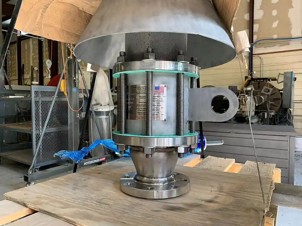
A tank blanketing valve is a self contained regulator that admits inert gas, most often nitrogen, into the vapor space of an atmospheric storage tank to hold a small positive pressure blanket as liquid level falls or vapor contracts with temperature. Setpoints are extraordinarily low by valve standards, 2.5 to 50 mbar, inches of water column in plant language, and the valve closes tight above setpoint so blanket gas is not wasted. Inlet nitrogen arrives from the site header at typically 2 to 10 bar and is reduced to the blanket setpoint inside the valve in one or two stages. Soft seats to Class VI shutoff are standard, because a blanket valve that weeps nitrogen quietly turns a gas conservation program into a monthly bill, and the valve works in choreography with venting hardware on the same tank nozzle rather than alone.
Procurement engineers buy these valves for edible oil and fat tanks where oxygen ruins product, for hygroscopic chemicals that pull water from ingressed air, for pharmaceutical solvents, for methanol and ethanol storage, and for produced water tanks where H2S bearing vapor must never meet air. The decision this page settles is narrow: spring operated or pilot operated architecture, the setpoint band and its spacing against the venting hardware, capacity sized to API 2000 inbreathing, nitrogen supply conditions, sense line arrangement, and the material and certificate set the service demands. The answer lands as an RFQ package, valve plus pressure vacuum relief valve plus emergency vent plus flame arrester plus depad path, because a blanket valve bought alone is half a system.
This page treats the tank blanketing valve as a purchasing object: how spring and pilot architectures hold mbar class setpoints, how API 2000 inbreathing numbers size the capacity, how the valve coordinates with venting and vapor recovery hardware on the same nozzle, and what setpoint, seat, sense, and material lines make a defensible RFQ. It is written for engineers who issue purchase specifications, not for readers who want a brochure summary.
Chapter 1 / 06
What a Tank Blanketing Valve Is and What Is Being Decided
Start with what the blanket is for, because every setpoint decision follows from the hazard. An atmospheric storage tank breathes: liquid pumped out leaves a vapor deficit, and day to night temperature swings expand and contract the vapor space. If nothing feeds gas in, the tank pulls air through its vents, and air means oxygen. Oxygen plus hydrocarbon or solvent vapor is a flammable mixture inside the tank headspace; oxygen plus hot edible oil is rancidity; moist air plus a hygroscopic chemical is water contamination; and air plus H2S laden vapor on produced water service is a toxicity and corrosion problem. The tank blanketing valve replaces the air with nitrogen fed at a few mbar, and its partner on the same nozzle, the pressure vacuum relief valve, protects the tank shell if the blanket system cannot keep up in either direction. The division of labor is plain: the blanketing valve feeds, the vent hardware relieves.
What is actually being decided in this purchase is a set of commitments. First, architecture: spring operated direct acting valves, the Series 30 class, are simple and economical but hold their setpoint inside a droop band, while pilot operated valves, the Series 20 class, hold plus or minus 2 mbar class accuracy, take higher supply pressures, and respond faster to pump out steps. Second, the setpoint band and its spacing: blanket setpoint, depad or vent opening, pressure vacuum relief valve settings, and emergency vent capacity must stack in the right order or the tank either wastes nitrogen or pulls air anyway. Third, capacity: inbreathing per API 2000, which means the maximum liquid outflow plus thermal inbreathing, not a rule of thumb. Fourth, the supply side: nitrogen header pressure, dew point, and whether reduction happens inside the valve or in stages. Fifth, the package: sense line routing, materials, certificates, and the venting hardware that shares the nozzle.
The setpoint language deserves respect. Blanket setpoints sit in the 2.5 to 50 mbar band, values so low that instrument technicians verify them with an inclined manometer rather than a gauge, and the choreography must stack: a typical arrangement holds the blanket at 5 mbar, opens the depad or vapor recovery path at a few mbar above that on fill, sets the pressure vacuum relief valve vacuum pallet at 15 mbar vacuum and its pressure pallet at 20 mbar as the backup layer, and reserves emergency venting for fire exposure sized per API 2000. Every device in that stack is doing a different job, and the blanketing valve is the only one of them whose job is to run continuously.
The economics run through nitrogen consumption. A tank farm blanketing program burns gas three ways: useful displacement on pump out, thermal breathing, and waste through seats and pilots that do not close tight. A Class VI soft seat with a low bleed pilot keeps the waste term small, while a valve that passes vapor through a worn seat quietly doubles a site's nitrogen bill for years before anyone audits it. Oversizing wastes in a different way: a valve sized for a pump out surge it never sees hunts and wears its seat, so capacity should be tied to the API 2000 arithmetic, not to the largest number in the catalog table.
Standards organize the datasheet. API 2000 governs venting of atmospheric and low pressure storage tanks: normal venting, inbreathing from liquid movement and thermal effect plus outbreathing on fill, and emergency venting for fire exposure, with the sizing tables every supplier quotation should reference. API 650 is the tank construction context that fixes the design pressure and vacuum the blanket system must respect. Seat tightness is stated in FCI 70-2 class terms, Class VI being the bubble tight class a blanket valve should carry. Sour service adds NACE MR0175 material requirements. A datasheet that quotes none of these is a price tag, not a tank protection specification.
The RFQ should also name the hardware that shares the duty, because none of these devices substitutes for another. The pressure vacuum relief valve is the protective sibling whose pallets open when the blanket system cannot keep up; a flame arrester belongs on any vent that opens to atmosphere where ignitable vapor can reach it, and the hooded arrester in the photograph above is exactly that class of hardware; emergency venting for fire exposure is a separate device, and unlike a rupture disk, which is a one shot burst element for pressure vessels, tank emergency vents reseat after the event; the nitrogen header itself arrives through a regulator station that may need its own pressure reducing valve when the header runs far above the 10 bar class. Specifying the whole package in one RFQ lets one supplier check nozzle sizes, setpoint stacking, and materials compatibility in a single pass.
Chapter 2 / 06
How Spring and Pilot Architectures Hold the Setpoint
The spring operated valve is the older and simpler architecture. Tank pressure acts on a diaphragm or piston loaded by a range spring; when vapor space pressure falls below setpoint, the imbalance lifts a poppet off its seat and admits nitrogen, and as pressure recovers the spring reseats the poppet. The physics is honest about its limit: as flow rises, the valve must open further against the spring, so outlet pressure droops below setpoint across the flow range. On a Series 30 class valve with a setpoint around 25 to 50 mbar, the droop band across rated flow can be a meaningful fraction of setpoint, which is acceptable when the tank tolerance band is wide and the outflow is steady, and is the reason larger or faster duty moves to pilot operation.
The pilot operated valve splits the job in two. A small pilot, sensing tank pressure, meters loading pressure onto the main valve diaphragm; the main valve opens fully with a small, relatively constant pressure drop because the pilot does the throttling and the main stage does the flow. The payoff is accuracy, plus or minus 2 mbar class control on Series 20 class hardware, higher inlet pressure tolerance in one stage, and fast response to a pump out step change. The cost is complexity: the pilot has orifices and a moving element that must stay clean, and some pilot designs bleed a continuous small flow to tank or atmosphere while operating, a term that belongs in the nitrogen consumption math alongside seat leakage.
Sensing arrangement is a decision, not a detail. The valve senses tank vapor space pressure either through an internal passage or through an external sense line run from the tank nozzle back to the valve diaphragm case. The external sense line, typically 12 mm tubing, senses tank pressure directly rather than at the valve outlet, which matters when the outlet piping is long or restricted; it is also the component that freezes in cold climates when moist gas condenses in the line, which is why cold climate specifications add a heat tracing cable along the sense run or specify dry nitrogen purge. Either way, the sense path must slope back to the tank so condensate drains rather than pools.
Seat construction decides the waste term. Blanket valves carry soft seats, an elastomer or PTFE disc against a metal or coated seat, qualified to Class VI bubble tight shutoff, with a fully guided stem so the disc does not chatter against the seat at partial lift. The seat is the component that weld slag finds first: one commissioning pass of line debris through a new nitrogen header scores every soft seat downstream, which is why the installation chapter insists on blowing lines down before the first valve goes on. Soft goods are FKM or EPDM by chemical compatibility, and on sour service the metallic parts carry NACE MR0175 requirements while the soft goods carry the chemical burden.
Capacity follows regulator arithmetic and API 2000 accounting. The valve is a reducing regulator whose flow depends on inlet pressure, setpoint, and effective orifice, and the sizing input is the tank's maximum inbreathing demand: liquid outflow converted to gas displacement, so a 100 m3/h pump out demands at least 100 m3/h of gas at blanket conditions, plus the thermal inbreathing allowance that API 2000 tabulates against tank volume and insulation condition. The valve capacity must cover that sum at the minimum credible nitrogen header pressure, and the quotation should state capacity at the actual supply pressure rather than at a flattering reference inlet.
The last mechanism worth understanding is the Joule Thomson effect on the gas itself. Nitrogen falling from 10 bar to a few mbar cools as it expands; at high flow the cooling is enough to freeze atmospheric moisture on valve bodies and sense lines in temperate climates and to ice regulators solid in cold ones. Two stage reduction, a first stage from the header down to 2 to 4 bar and the blanket valve taking the remainder, spreads the expansion and the cooling across two bodies; on long runs from high headers this is standard practice, and the upstream pressure reducing valve is often the cheaper place to take most of the drop.
Chapter 3 / 06
Types, Construction, and Duty Boundaries
Spring operated direct valves, the Series 30 class, are the workhorse of small and medium tankage. One moving assembly, a spring range spanning roughly 25 to 50 mbar setpoints, body options in aluminium or 316 stainless steel, and threaded or flanged connections in the 1 to 2 inch class make them the economical choice where outflow is steady and the tank tolerance band is forgiving. Their droop characteristic means setpoint and capacity trade against each other, so the datasheet should be read as a band rather than a line, and the application table later in this chapter shows where that band is acceptable.
Pilot operated valves, the Series 20 class, hold plus or minus 2 mbar class accuracy, accept inlet pressures toward the top of the 2 to 10 bar range in one stage, and respond quickly to pump out steps. They suit large tanks, high outflow rates, and sites where nitrogen conservation is audited, because tight control at a low setpoint keeps the blanket above minimum without drifting high enough to push vapor out the vent. The pilot's cleanliness requirement is real but modest, and the annual check of its orifices and screen belongs in the maintenance schedule.
Supply architecture is the third type axis. Single stage valves take the header pressure directly and are right when the header is stable at 2 to 4 bar. Two stage systems interpose an upstream pressure reducing valve or regulator station so the blanket valve sees a constant moderate inlet regardless of header swings, which stabilizes capacity, reduces icing exposure, and lets the blanket valve be a smaller, more accurate device. On sites where the nitrogen header runs above 10 bar or swings widely, two stage is not an optimization, it is the design.
Installation hardware completes the type picture. The valve outlet connects to the tank vapor space through a nozzle whose size the valve outlet should match, never reduced; isolation is a simple ball valve at the inlet and, where maintenance without tank opening is wanted, at the outlet too. The flame arrester question belongs to the vent path rather than the nitrogen path: any opening that can discharge tank vapor to atmosphere, the PVRV outlet on open service, the depad vent terminus if it is open, carries an arrester where the hazard analysis requires one. Sense lines are run as discussed in chapter 2, sloped, supported, and heat traced where freezing is credible.
Boundaries deserve one blunt paragraph. The blanketing valve is a service regulator, not overpressure protection: nothing it does replaces the pressure vacuum relief valve or the emergency vent, and nothing in its certification qualifies it as a safety relief valve for a pressure vessel, which is a different device family with different codes. It does not create vacuum; it feeds gas so vacuum does not develop, and if its capacity is exceeded the PVRV vacuum pallet admits air as the deliberate last resort. It is not a vapor recovery device either: on fill, outbreathing leaves through the depad path to a vapor recovery unit or a controlled vent, and the blanket valve's job ends at holding the floor. The table below consolidates the architectures.
Architecture
Control accuracy
Typical inlet
Response character
Best duty
Spring operated direct, Series 30 class
Droop band; setpoints about 25 to 50 mbar
2 to 4 bar typical
Moderate; droops with flow
Small and medium tanks, steady outflow, simple plants
Pilot operated, Series 20 class
Plus or minus 2 mbar class
To 10 bar and above
Fast to pump out steps
Large tanks, high outflow, audited N2 consumption
Two stage with upstream reduction
Pilot accuracy on staged drop
Headers above 10 bar
Stable across header swings
Long runs from high headers, cold climate icing control
Chapter 4 / 06
Key Specification Parameters
The table below decodes the datasheet lines that decide whether a quoted valve matches the tank. Each row is purchase defining; the paragraphs after the table explain what to demand and what a weak answer looks like.
Attribute
Typical range or options
What it decides
Setpoint range and accuracy
2.5 to 50 mbar; pilot plus or minus 2 mbar class; spring droop band
Blanket pressure, nitrogen usage, and spacing to vent settings
Capacity at supply pressure
Sized to API 2000 inbreathing: maximum outflow plus thermal
Vacuum protection margin and freedom from hunting
Inlet supply range
2 to 10 bar; staged reduction above that
Architecture, staging, and icing exposure
Seat tightness
Class VI soft seat, guided stem
Nitrogen consumption and product protection
Body and soft goods
Aluminium or 316 stainless; FKM or EPDM; NACE MR0175 option
Flanged or threaded, outlet matched to tank nozzle
Velocity, pipe sizing, and installation fit
Pilot bleed and consumption
Continuous bleed stated by maker; low bleed designs available
Standing nitrogen consumption term
Certificates
Material certs; NACE for sour; leak test evidence
Traceability and sour service acceptance
The setpoint row and the capacity row travel together, because the choreography is the specification. Write the stack explicitly: blanket setpoint at, say, 5 mbar; depad or vapor recovery opening a few mbar above it on fill; pressure vacuum relief valve settings, for example 15 mbar vacuum and 20 mbar pressure, as the backup layer; emergency vent per API 2000 fire sizing on its own path; flame arrester wherever the vent is open to atmosphere. A supplier quotation that returns a blanket valve without confirming the stack against the tank's design pressure and vacuum is quoting a widget, not a system, and the error surfaces as either wasted nitrogen or a tank that pulls air in spite of the blanket.
Instrumentation makes the mbar world visible. The vapor space pressure logged by a pressure transmitter gives the control room the one trend that diagnoses everything: a flat line says the system is quiet, sawtooth says hunting, and a slow climb says a passing seat or a misbehaving depad. Where the site wants barometric independent records, an absolute pressure transmitter on the vapor space removes weather driven swings from the trend, which matters when the whole working band is a few mbar wide. Local checks stay analog: a pressure gauge on the nitrogen header confirms supply, a manometer, inclined for the range, verifies setpoint against the transmitter, and a differential pressure transmitter across the upstream supply filter catches the slow blockage that otherwise looks like valve aging. None of these instruments is exotic, and all of them belong on the same purchase order.
Level instrumentation closes the sizing loop and shares the shutdown with the vent hardware. The maximum outflow that sizes the valve comes from the pump and unloading schedule, and the inventory level transmitter trend is the honest record of it; a radar level meter serves most storage tanks for inventory, an ultrasonic level meter covers simpler service where vapor conditions allow, and a magnetic level gauge at the gauger platform remains the local readout everyone trusts during a power failure. When the level transmitter trend and the nitrogen consumption trend are read together, tank breathing becomes an auditable number instead of a monthly gas bill surprise.
The coordination table below is the form a specification meeting can argue from, one row per device on or near the nozzle.
Device
Setpoint or trigger
Function in the stack
Tank blanketing valve
Opens at blanket vacuum setpoint; holds about 5 mbar
Feeds nitrogen on pump out and thermal inbreathing
Depad valve or VRU path
Opens on fill pressure rise, a few mbar above blanket
Sends excess vapor to recovery or controlled vent
Pressure vacuum relief valve
Vacuum 15 mbar, pressure 20 mbar class
Backup vacuum and pressure protection of the shell
Emergency vent
API 2000 fire exposure sizing
Rapid overpressure relief, reseats after event
Flame arrester
Passive, end of line or in line
Stops flame path on vents open to atmosphere
N2 supply regulator station
Holds 2 to 4 bar at the valve inlet
Stabilizes capacity and limits JT icing exposure
Chapter 5 / 06
Selection Decision Factors and RFQ Language
The decision sequence is short enough to run as a checklist in a specification meeting, and each step eliminates a class of quotations before price comparisons begin.
Establish the reason for blanketing in writing: flammable vapor air exclusion, product oxidation, moisture exclusion, or toxic vapor containment. The reason sets the tightness and the monitoring.
Fix the tank envelope: size, design pressure and vacuum per API 650 context, and the nozzle schedule the valve must match.
Compute inbreathing per API 2000: maximum liquid outflow plus thermal allowance, at the worst credible operating temperature swing.
Choose the architecture: spring operated for steady duty and forgiving bands, pilot operated for large tanks, high outflow, and audited consumption, two stage for high or unstable headers.
Write the setpoint stack: blanket, depad, PVRV vacuum and pressure, emergency vent, with every number in mbar and in the right order.
Fix the supply side: header pressure range, dew point, staging, and filter provision ahead of the pilot.
Fix materials and certificates: aluminium or 316 stainless bodies, FKM or EPDM soft goods by chemical, NACE MR0175 where sour.
Specify the package: valve, venting hardware, arrester coverage, and the isolation and check hardware around each, so one supplier verifies the stack.
Against neighboring hardware, the comparison a specifier actually needs runs as follows, and it belongs here in the selection chapter rather than in the page title. A pressure reducing valve or regulator station upstream is not a substitute for the blanket valve: it holds bar class pressures on the header, while the blanket valve's whole craft is the mbar band at the tank. The pressure vacuum relief valve is the protective sibling, not a feeding device, and it must never be told to do the blanketing valve's job. A rupture disk is a one shot element for vessel overpressure and has no place in the repeatable breathing duty of an atmospheric tank. The safety relief valve belongs to pressurized systems and code vessels, a different world from API 650 tankage. On the piping around the package, isolation is a ball valve at small bore, a butterfly valve on larger vapor headers where low pressure drop at low pressure matters, and a gate valve on the nitrogen header where the maker's pressure class suits; a check valve in the nitrogen line after the isolations is cheap insurance that tank vapor never backfeeds into a site header during an upset. Each of these is a line item, none is a substitute.
The application map below turns those boundaries into a table the project file can carry.
N2 dew point against hygroscopic product; setpoint stack order
Hygroscopic chemicals
316 stainless, tight seat, traced sense line where cold
Moisture ingress math; sense line routing and drainage
Produced water with H2S
NACE MR0175 materials; fuel gas alternative where N2 absent
Sour certificates; depad routing to flare or VRU
Pharmaceutical solvents
316L, low bleed pilot, documentation package
Batch protection evidence; certificates with the shipment
Cold climate terminals
Two stage reduction, traced and drained sense line
Joule Thomson icing at maximum flow; heat tracing cable listing
The RFQ block should be written once and reused. A complete block reads: tank size and design pressure and vacuum; maximum pump out rate and the API 2000 inbreathing computation; blanket setpoint with tolerance and the full setpoint stack against the vent hardware; nitrogen supply pressure range and dew point; sense arrangement, internal or external, with routing and tracing; outlet size matched to the nozzle; seat class and the nitrogen consumption guarantee basis; body, soft goods, and certificate set including NACE applicability; and the coordination package, vent valve, emergency vent, arrester, and the isolation and check hardware around each. A quotation returned without capacity at the stated supply pressure and without the setpoint stack confirmed is incomplete at any price.
Chapter 6 / 06
Installation, Standards, Failure Modes, and Maintenance
Installation quality decides whether the seat survives its first year. Nitrogen headers are blown down and cleaned before the first blanketing valve goes into service, because weld slag and pipe scale from new construction score Class VI seats on the first high flow pass; a Y strainer and a ball valve at each inlet give the line a chance to be cleaned again later without breaking the tank blanket. The valve outlet rises to the vapor space nozzle without reductions, and the line slopes and drains so condensate never pools against the valve body. The header side is not forgotten: the line isolating the run from the site nitrogen main is a gate valve suited to the header class, with the supply pressure gauge visible from grade so operations reads header health without climbing. Sense lines run sloped back to the tank, supported, and in freezing climates carry a heat tracing cable with its listing checked against the area classification. Where the outlet path passes near hot equipment, an expansion allowance in the tubing prevents the thermal growth from loading the valve body.
Commissioning proves the stack, not just the valve. Setpoint is verified with an inclined manometer against the diaphragm case tap while the transmitter reads in the control room, so the two agree before the tank is trusted to them. The response test simulates a pump out step, opening a downstream vent briefly or starting the transfer pump against a held level, and confirms the valve feeds without hunting and the pressure vacuum relief valve stays closed throughout. Nitrogen consumption is baselined over the first weeks of normal operation, because that number, liters per hour on a quiet week, is the seat health reference for years.
The standards frame is compact and belongs in the RFQ by name. API 2000 fixes the venting arithmetic, inbreathing, outbreathing, and emergency, that sizes every device in the stack. API 650 is the tank context that fixes design pressure and vacuum limits the stack must respect. FCI 70-2 defines the seat leakage class behind the bubble tight claim. NACE MR0175 governs materials where sour service applies. A specification that cites these transfers the burden of proof to the supplier, which is where it belongs.
Failure modes follow a short and weather aware list. Seat wear from line debris leads: nitrogen consumption creeps up months before anything alarms, which is why the consumption trend is the primary diagnostic. Pilot blockage follows on pilot operated valves, showing as sluggish response or a stuck open condition, and the annual pilot screen and orifice check exists to prevent it. Sense line freezing is the cold climate signature: the valve stops sensing, holds its last position, and the tank either overpressures the vent stack or pulls toward vacuum until the ice clears; tracing and drainage are the preventives. Hunting comes from oversizing: a valve sized for a surge it never sees cycles continuously at partial lift, wearing its seat and hammering its stack, and the fix is right sizing, not adjustment. Joule Thomson icing at high flow coats the valve body and the upstream regulator on humid days, and two stage reduction spreads the cooling. Spring creep and soft goods swelling close the list on old installations, read as a setpoint that has drifted from the commissioning record.
Maintenance is a quarterly walk with an annual service. Quarterly, read the vapor space trend from the pressure transmitter and the nitrogen consumption log together: a quiet flat line with steady consumption says leave it alone, a rising baseline says inspect the seat at the next opportunity. Annually, verify setpoint with the manometer, exercise the inlet ball valve and the check valve, stroke the butterfly valve on the larger vapor headers, inspect the sense line for drainage and tracing condition, and check the upstream filter with the differential pressure transmitter reading; on instrumented tanks, file the pressure transmitter trend and the absolute pressure transmitter record alongside the local pressure gauge readings so the next audit compares like with like. At the tank shutdown shared with the vent hardware, lift and inspect the blanketing valve seat, clean the pilot screen, and check the pressure vacuum relief valve pallets and the flame arrester element in the same work order, because one crane permit covers all of it. Cross check the inventory level transmitter trend, or the radar level meter where that is the inventory device, and the ultrasonic level meter or magnetic level gauge readings against the nitrogen consumed, because breathing that does not match level movement is the earliest sign of a seat or stack problem. A tank that is not audited is a tank that decides its own maintenance date.
FAQ
When does a storage tank need blanketing at all?
Blanket a tank when the vapor space must stay away from air or moisture: flammable products where oxygen plus vapor forms an ignitable mixture, edible oils and fats that oxidize, hygroscopic chemicals that absorb water from ingressed air, pharmaceutical solvents, and produced water where H2S bearing vapor must not meet oxygen. If none of those apply and the product is insensitive, simple venting with a pressure vacuum relief valve is the honest, cheaper answer.
Spring operated or pilot operated: which do I buy?
Buy spring operated, the Series 30 class, for small and medium tanks with steady outflow and a forgiving pressure band: one moving assembly, setpoints around 25 to 50 mbar, lowest cost, honest droop. Buy pilot operated, the Series 20 class, for large tanks, high pump out rates, headers toward 10 bar, and sites that audit nitrogen consumption, because plus or minus 2 mbar class control at a tight setpoint is what keeps gas bills down. Two stage designs with upstream reduction serve high or unstable headers and cold climates.
How do I set the blanketing setpoint against the vent settings?
Stack the setpoints in writing and in mbar. Hold the blanket at the bottom, for example 5 mbar; open the depad or vapor recovery path a few mbar above that on fill; set the pressure vacuum relief valve vacuum pallet deeper, for example 15 mbar vacuum, and its pressure pallet higher, for example 20 mbar, as backup; size the emergency vent for fire per API 2000 on its own path. Every layer must be able to do its job without the layer below blocking it, and the supplier should confirm the stack against the tank design limits.
How is blanketing valve capacity sized?
Per API 2000 inbreathing: convert the maximum liquid outflow to gas displacement, so a 100 m3/h pump out needs at least 100 m3/h of gas at blanket conditions, then add the thermal inbreathing allowance the standard tabulates against tank volume and insulation. The valve capacity must cover the sum at the minimum credible nitrogen header pressure, not at a flattering reference inlet. Oversizing is a fault, not margin: an oversized valve hunts, wears its seat, and upsets the stack.
Why does nitrogen consumption creep up over the years?
Three usual causes. First, seat wear: debris or age keeps the soft seat from closing bubble tight, and the bleed is invisible except in the gas bill, which is why the consumption baseline taken at commissioning is the primary diagnostic. Second, pilot bleed on pilot operated valves, a continuous small flow by design on some models; low bleed designs minimize it. Third, a drifting setpoint from spring creep or soft goods swelling holds the blanket higher than needed, pushing vapor out the vent. Quarterly trend reading catches all three.
What causes blanketing valves to freeze or ice up?
Two mechanisms. Moist gas condenses in an external sense line and freezes in cold weather, so the valve stops sensing tank pressure; the preventives are a sloped, drained sense run and a heat tracing cable listed for the area. Separately, the Joule Thomson effect cools nitrogen expanding from high header pressure at high flow, icing the valve body and any upstream regulator; two stage reduction spreads the expansion and the cooling across two bodies, which is standard practice on high headers and in cold climates.
What belongs in the tank blanketing RFQ package?
Tank size with design pressure and vacuum; maximum pump out rate and the API 2000 inbreathing computation; blanket setpoint with tolerance and the full setpoint stack; nitrogen supply pressure range and dew point; sense arrangement and routing; outlet size matched to the nozzle; seat class with the consumption guarantee basis; materials and certificates including NACE applicability; and the coordination hardware: vent valve, emergency vent, flame arrester where the vent is open, and the isolation and check valves around each. A quotation without capacity at stated supply pressure is incomplete at any price.