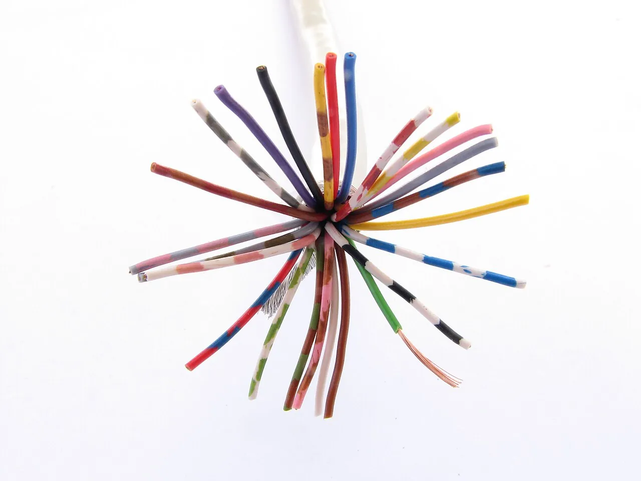
Heat tracing cable is a resistance heating element manufactured as a cable and run along pipes, vessels, and instrument lines under the thermal insulation, where it replaces the heat the process loses to ambient and holds the contents at a chosen maintain temperature. Where a power cable or a control cable carries energy to a load, the heat tracing cable is itself the load: every meter of it converts electrical power into watts of heat exactly where the pipe needs them. Self-regulating types, the dominant family, rate from 3 to 65 W per meter at 10 deg C and adjust their own output as the pipe warms, while constant wattage and mineral insulated types hold fixed output to much higher temperatures.
Procurement engineers meet electric heat tracing on outdoor water and fire mains that must not freeze, on heavy fuel oil and sulfur lines that must stay pumpable, on asphalt and bitumen at 150 deg C class, and on instrument impulse lines that would block with ice on a minus 20 deg C night. The decision this page settles is narrow and calculable: how many watts per meter the pipe actually loses, which cable family holds the required maintain temperature, what control and protection hardware keeps the circuit safe, and what an RFQ must state so the delivered circuits survive the first record cold snap. Every chapter feeds that RFQ line set.
This page treats the heat tracing cable as a purchasing object: how the self-regulating polymer core actually governs power output, where each cable family's maintain temperature ceiling sits, how watts per meter of heat loss are calculated and margined, which control and protection hardware belongs on the circuit, and how all of it combines into a defensible RFQ. It is written for engineers who issue purchase specifications, not for readers who want a brochure summary.
Chapter 1 / 06
What a Heat Tracing Cable Is and What Is Being Decided
A heat tracing cable is a designed heater that happens to be shaped like a cable. It contains either a resistive heating element or a conductive heating core, electrical insulation rated for the process exposure, a metallic braid that serves as the protective earth and mechanical armor, and an outer jacket chosen against the chemicals and abuse of the plant. It is strapped to a pipe, covered by thermal insulation and cladding, and connected to a supply through a junction box or a cold lead, so that from the outside a traced line looks like any insulated line except for the warning labels. It shares raceway hardware with ordinary wiring, and a cold lead may ride a cable tray back to the panel, but the heated section stays on the pipe under the cladding, never in the tray with the instrument wiring. Its single job is thermal: hold the contents at or above a maintain temperature, whether that maintain point is 5 deg C to keep water liquid or 145 deg C to keep sulfur molten.
What is actually being decided in this purchase is a thermal balance, and the buyer who skips the balance buys the wrong cable with confidence. The pipe loses heat through its insulation at a rate set by pipe size, insulation type and thickness, maintain temperature, and the coldest design ambient; the cable must deliver at least that many watts per meter at the maintain temperature, with margin, over the whole length including valves and flanges that leak extra heat. On top of the thermal decision sit electrical decisions, circuit length per breaker, cold start current, residual current protection, and control decisions, from a simple mechanical thermostat to a surface temperature sensor such as an RTD PT100 wired into a controller in the PLC. A purchase order that names only a cable wattage has decided the least important number on the datasheet.
Boundary against the neighbors keeps the specification honest. A heat tracing cable shares raceways, glands, and labels with a control cable or a power cable, but it is neither: it dissipates its entire carried power as heat instead of delivering it, and it must never be bundled into the moving raceways of machinery, so it never enters a cable drag chain or any flexing service. It is controlled by, but is not, a thermostat or a temperature transmitter; those are separate purchases covered in the selection chapter. It is not a fire safety device: a heat detector watches for fire, while tracing cable at most causes a warm spot, and the two share nothing on a drawing except the word heat. And it is not tank heating panels or immersion heaters, which serve vessels rather than lines, although the same suppliers and standards cover them.
The discipline is old and well standardized. IEEE 515 is the canonical standard for the testing, design, installation, and maintenance of electric heat tracing for industrial process applications, and IEC 62395 covers surface heating systems on the international side. In North American wiring practice, NEC Article 427 governs fixed industrial process heating equipment, from branch circuit sizing to marking, and IEC 60079 with ATEX governs hazardous area installations where the cable, terminations, and temperature class must be certified as a system. Those four names organize the datasheet the same way API and ISA names organize a valve datasheet, and a quotation that cites none of them is a price tag.
The economics decision sits at the system level and belongs in the RFQ round, not after it. Steam tracing, the incumbent technology in older plants, runs steam lines along the pipe with a steam trap at every low point; electric heat tracing replaces the steam with cable, a panel, and controls. The two options are compared honestly inside the selection chapter, because the right answer depends on steam availability, trap maintenance history, and the maintain temperature demanded. What this page fixes first is what the electric option actually is, so that comparison starts from engineering reality rather than from vendor folklore.
Chapter 2 / 06
How Self-Regulating Physics Works and How Heat Loss Is Sized
The self-regulating core is a conductive polymer extruded between two parallel nickel-plated copper bus wires. Microscopically the polymer is an insulating matrix loaded with conductive carbon particles; current flows through the particle to particle paths that touch across the matrix, and those paths are the heating element. When the cable is cold the polymer contracts, particle contact improves, resistance falls, and power output rises. When the cable warms the polymer expands, contacts break, resistance climbs, and power output falls on a steep curve. The result is a heater whose output per meter varies continuously with its own local temperature, typically from full rated output at 10 deg C down to a fraction of it at the maintain point and toward zero as the cable approaches its exposure limit.
Two engineering consequences follow directly from that construction. First, the cable cannot burn itself out from self-heating: wherever it gets hot, its power collapses, so a self-regulating cable overlapped on itself, while still poor practice, does not run away the way a fixed resistance heater would. Second, because the two bus wires run the full length in parallel, the cable is cut to length in the field; each meter draws what its own temperature demands, so a meter crossing a cold flange draws more power than a meter under warm insulation without any control wiring. Rated outputs run from 3 W per meter for long freeze protection runs up to 65 W per meter at 10 deg C for heavy process duty, and the output at the actual maintain temperature, published in the family power-temperature table, is the number the thermal calculation must use, never the rated headline figure.
The other families heat by plain resistance instead of polymer physics, and the difference shows in their behavior. A constant wattage zone cable wraps series resistance wire in zones around the bus, giving every meter the same fixed output regardless of temperature; it can overheat if crossed on itself, and it is cut or terminated only at zone marks printed on the jacket. A mineral insulated cable, MI for short, is a single series heating conductor embedded in compacted magnesium oxide powder inside a metal sheath, copper sheathed for lower temperatures and Inconel sheathed for hot and corrosive duty; it holds the highest maintain temperatures and power densities but is rigid, and it is factory fabricated to exact length with welded end seals and cold tails, so a field measurement error becomes a factory remake rather than a coil of scrap.
Heat loss per meter is the calculation the whole purchase hangs on, and it is one equation in words: the heat flow from the pipe through cylindrical insulation equals two pi times the insulation thermal conductivity times the temperature difference between pipe and ambient, divided by the natural logarithm of the outer insulated radius over the bare pipe radius. Insulation conductivity is taken at mean insulation temperature, the difference is maintain temperature minus minimum design ambient, and the answer in watts per meter is then increased by design margin, commonly 10 to 20 percent, plus a wind allowance where outdoor cladding faces wind, since moving air strips the still air film the calculation assumes. Typical results for mineral wool or closed cell insulation of 50 mm thickness: a DN 25 water line holding 5 deg C at minus 20 deg C ambient loses on the order of 5 to 8 W per meter, a DN 100 line of the same service closer to 15 to 20, and a DN 100 line holding molten sulfur at 140 deg C in plus 5 deg C ambient loses tens of watts per meter and needs the higher output families.
Fittings add equivalent length, and forgetting them is how circuits end up short. Each flange pair behaves roughly like an extra meter of pipe in heat loss terms, a valve like 2 to 4 meters depending on size and bonnet area, and pipe supports and shoes leak their own extra heat through the metal to steel. Standard practice therefore spirals two to three meters of additional cable across each valve, one across each flange pair, and loops extra at each support, so the purchased length is pipe length plus the fittings allowance, not pipe length alone. The cable that ends exactly at the far flange with nothing left for the valve before it is the most common commissioning discovery on traced projects.
The electrical behavior at start completes the physics picture. A cold self-regulating cable draws 1.2 to 2 times its steady state current, and at minus 20 deg C start conditions that inrush can sit near the top of the band for the first minutes; the circuit breaker or fuse must be sized for cold start, and the maximum circuit length tables published per family exist precisely to bound that inrush and the volt drop along the bus wires. Long self-regulating circuits also carry significant distributed capacitance, and on 230 V circuits of a hundred meters and more the charging current can nuisance-trip a 30 mA residual current device; the honest design answers are shorter circuits, more feeds, or an RCD scheme designed to the local electrical code rather than a bigger device bolted on later. The tinned copper braid is the protective earth and must be landed at every supply point; an ungrounded tracing circuit is a code violation before it is a hazard.
Chapter 3 / 06
Cable Families, Construction, and Duty Boundaries
Four families cover essentially all industrial line heating duty, and the family sets the maintain temperature ceiling long before brand matters. Self-regulating cable serves freeze protection and moderate process maintain duty, with typical continuous maintain temperatures to 110 or 150 deg C depending on grade and short exposure limits above 200 deg C during steaming or upset. Power-limiting cable, a higher temperature parallel construction with alloy and polymer heating zones, extends parallel convenience to maintain temperatures around 200 to 230 deg C and tolerates longer circuits. Constant wattage zone cable delivers fixed output per meter for duties where output must not fall as the pipe warms. Mineral insulated cable owns the top of the range, with maintain capability to roughly 500 deg C class and power density to about 150 W per meter, in a rigid metal sheath that survives process temperatures and corrosion that would destroy polymer jackets. The tradeoffs between the families, in the selection sense, are worked through in chapter 5; this chapter fixes what each construction is.
Within self-regulating lines, grades are chosen by output and temperature class. Freeze protection of water lines and fire mains is usually served by the 5 to 15 W per meter classes, enough to hold 5 deg C against modest heat loss; process maintenance such as heavy fuel oil at 40 to 60 deg C takes the 10 to 20 W per meter classes; higher outputs near 30 to 65 W per meter cover large bore and hot services short of the power-limiting range. Construction layers matter as much as output: the fluoropolymer inner insulation sets the chemical and temperature envelope, the tinned copper braid provides the earth and a degree of mechanical protection, and the outer jacket, fluoropolymer for chemical areas or stainless steel overbraid for abrasion and foot traffic, decides what the cable survives on the outside of the pipe.
Termination hardware is part of the family, not an accessory. Self-regulating and zone cables need a braid landing, an end seal, and either a junction box entry through a proper cable gland or a factory cold lead; hazardous area versions require certified end seals and junction boxes because an uncertified termination voids the system certification. MI cable arrives terminated by the factory with welded seals and cold tails to the site's measured lengths. Every family marks the maximum exposure temperature, and the rule is absolute: the cable must survive the highest temperature the traced line can reach, including steam out and cleaning cycles, not merely the maintain point. A cable rated 150 deg C maintain on a line steamed at 180 deg C survives exactly until the first steam out.
Duty boundaries keep the families in their lanes. Self-regulating owns freeze protection and viscosity services up to its maintain ceiling because it is field cut, forgiving, and self-limiting. Power-limiting takes the parallel-cable duties one temperature band higher. Zone constant wattage suits fixed output needs and long straight runs. MI takes hot asphalt and sulfur transfer, superheated steam tracing replacement, and anything corrosive that must be metal sheathed. Below a certain scale, tank and hopper duties move to heating panels rather than cable, and indoor utility lines in heated buildings often need no tracing at all, a boundary the energy audit should catch before the purchase order does. The table below compresses the family map.
Family
Maintain temperature class
Output range
Field cut to length
Typical duty
Self-regulating
to 110 or 150 deg C typical
3 to 65 W/m at 10 deg C
Yes, anywhere
Freeze protection, fuel oil, water lines
Power-limiting
about 200 to 230 deg C
mid to high W/m grades
Yes, with limits
Hot process maintain, longer circuits
Constant wattage zone
grade dependent, mid range
fixed W/m by zone
At zone marks only
Fixed output duties, straight runs
Mineral insulated
to about 500 deg C class
to about 150 W/m
No, factory fabricated
Sulfur, asphalt, hot and corrosive lines
Chapter 4 / 06
Key Specification Parameters
The table below decodes the datasheet lines that decide whether a quoted cable matches the traced system. Each row is purchase defining; the paragraphs after the table explain what to demand and what a weak answer looks like.
Attribute
Typical range or options
What it decides
Maintain temperature
5 deg C freeze class to 500 deg C class
The thermal duty the cable must hold continuously
Maximum exposure temperature
150 to 480 deg C by family and grade
Survival through steam outs, cleaning, upsets
Power output
3 to 65 W/m at 10 deg C; fixed grades for zone and MI
Output at maintain temperature against calculated loss
Supply voltage
120 or 230 V AC typical
Panel design, volt drop, and circuit length ceiling
Maximum circuit length
Vendor table, tens to about 200 m by grade and volts
Feeder count, breaker count, and inrush behavior
Cold start current
1.2 to 2 times steady state
Breaker and fuse sizing at minimum ambient
Temperature class, hazardous areas
T6 to T3 marking per IEC 60079
Acceptance in classified areas with certified terminations
Braid and jacket
Tinned copper braid; fluoropolymer or SS overbraid
Earthing, chemical and mechanical survival
Minimum install temperature and bend radius
typically minus 40 deg C install; bend about 5 times width
Winter construction practice without core damage
The power output row is where quotations are won and lost honestly. The rated watts per meter at 10 deg C is a catalog anchor, but the selection must be made at the maintain temperature: a 15 W per meter self-regulating grade may deliver half of that at 60 deg C pipe temperature, and the vendor power-temperature table, not the model name, is the number that goes into the thermal balance. Demand that table with the quotation, along with the output at minimum ambient for inrush estimation, and check the fitting allowances of chapter 2 against the quoted circuit lengths. A supplier who quotes a model number without the power-temperature curve has left the engineering to the buyer.
The electrical rows deserve equal attention because they decide the panel. Maximum circuit length per family per voltage is published to bound inrush and volt drop; stringing a self-regulating circuit beyond the table starves the far end at cold start even when the breaker holds. Breaker or fuse sizing uses cold start current at minimum ambient, and the residual current scheme must be reviewed on long circuits for the capacitance effect described in chapter 2. In hazardous areas the temperature class, T6 for the lowest auto-ignition margin through T3 for hotter ratings, is a system property: cable, end seal, junction box, and connection must all carry the marking, per IEC 60079 and the ATEX directive, and one uncertified component voids the installation.
The comparison table below puts the four families against each other on the parameters that drive selection, in the sense used in the selection chapter: it summarizes boundaries, and the purchasing decision itself is worked through there against real duties.
Parameter
Self-regulating
Power-limiting
Constant wattage zone
Mineral insulated
Maintain ceiling
110 to 150 deg C
200 to 230 deg C
mid range by grade
about 500 deg C class
Output at temperature
Falls as pipe warms
Falls gently
Fixed per zone
Fixed by conductor
Crossing itself
Tolerated in moderation
Allowed with limits
Avoid, hot spot risk
Avoid, hot spot risk
Field cutting
Anywhere
Allowed with rules
Zone marks
No, factory lengths
Circuit length
Short to medium
Longer
Medium
Long, low current
Relative cost per meter
Lowest of the four
Moderate
Moderate
Highest, plus fabrication
Read the comparison as a shortlist filter, not a verdict. The maintain ceiling row eliminates families first, then cut-to-length and circuit length rows decide panel and installation practice, and cost lands last. Grade selection inside a family, 10 versus 15 versus 20 W per meter self-regulating for example, is then made against the calculated heat loss with margin, using the power-temperature table, and the chosen grade goes into the RFQ by its full designation, not its nickname.
Chapter 5 / 06
Selection Decision Factors and RFQ Language
The decision sequence is short enough to run as a checklist in a specification meeting, and each step eliminates a class of quotations before price comparisons begin.
Fix the thermal duty first: maintain temperature, minimum design ambient with a return period, wind exposure, pipe sizes, insulation type and thickness, and a fittings schedule listing every valve and flange.
Calculate heat loss per meter per line size and add the design margin plus wind allowance; this is the number every later decision serves.
Eliminate cable families by maintain and exposure temperature, including steam out; what survives is the shortlist.
Select the grade from the power-temperature table so output at maintain temperature covers calculated loss with margin.
Choose the control scheme against the allowed temperature band: ambient switching, line sensing, or full proportional control, plus a hardwired high limit where the process demands it.
Design the electrical panel: circuit lengths within vendor maximums, breaker sizing for cold start, residual current scheme per code, braid earthing at every feed.
Fix hazardous area requirements if any: temperature class, certified end seals and boxes, and IEC 60079 or ATEX documentation as a system.
Write the verification evidence into the purchase order: megohm test values at receipt, power-temperature data, circuit length tables, and installation instructions per IEEE 515 or IEC 62395.
Electric versus steam tracing is the first fork, and it belongs to the site, not the vendor. Steam tracing delivers heat from plant steam through a tracer tube under the cladding, with a steam trap at every low point and a trap station every 30 to 50 meters; it works well where steam is abundant, maintain temperatures are moderate to high, and the plant tolerates the maintenance load, because every steam trap is a live failure point that either leaks energy or freezes and blocks. Electric heat tracing costs more to install per circuit and buys precise control, per circuit metering, no traps, no condensate, and no leak risk into the insulation; it wins decisively on long remote runs, on instrument lines, and wherever the steam balance does not already exist. The honest engineering comparison counts steam trap maintenance and steam energy on one side and electricity plus controls on the other, over ten years, and it is made once per plant rather than once per project.
Control selection follows the allowed temperature band. The cheapest credible scheme for freeze protection is ambient switching: a thermostat or contactor senses outdoor air and switches whole tracing groups when ambient falls below about 5 deg C, crude but effective for water lines. A line-sensing mechanical thermostat, bulb clamped to the pipe under the insulation, holds a setpoint within a few degrees for viscosity services and needs nothing more than wiring. Tight maintenance, sulfur and asphalt duty, and energy accounting move up to a surface-mounted RTD PT100 or a thermocouple with an electronic controller switching the circuit through a contactor or solid state relay, and from there into the control system: the temperature sensor reading can drive a local panel or ride a temperature transmitter into the PLC, where alarming, trending, and duty logging happen in software. A thermocouple suits high temperature surfaces where its simpler construction survives, while the RTD PT100 is the default for accuracy and interchangeability. Mount any pipe-skin temperature sensor at least a pipe diameter away from the cable run, so the controller sees metal temperature rather than heater output, and never bury the sensing element under the cable itself. For hardwired protection against control failure, a temperature switch on the pipe skin drops the circuit independently, a layer that matters on heat sensitive contents. Vessel and tank services read product temperature with a sensor in a thermowell rather than a surface clamp, since the fluid, not the wall, is the process variable.
Two boundaries belong here because they are purchasing decisions, not installation notes. First, this system is not fire detection: a heat detector and its alarm loop are safety equipment under fire codes, and no part of heat tracing, its controls, or its alarms substitutes for one; when a tracing circuit overheats, the correct response is electrical isolation and repair, not a reinterpretation of the event as detection. Second, panel segregation is part of the electrical purchase: tracing panels are resistive and clean, so they share an MCC happily, but keep their feeds documented apart from motor and VFD circuits so that a drive fault investigation never masks a tracing group, and never let convenience wiring bundle a tracing run into signal raceways where induction adds noise to instrument cable.
The application map below turns the family and control logic into a table the project file can carry into the RFQ round.
Application
Construction to specify
Check before order
Water and fire main freeze protection
Self-regulating 5 to 15 W/m, ambient switching or line thermostat
Record low ambient; insulation condition; support shoes allowance
Instrument impulse line freeze protection
Low output self-regulating, line sensing control, small panels
Circuit length per impulse bundle; end seal quality
Heavy fuel oil viscosity maintain, 40 to 60 deg C
Self-regulating 10 to 20 W/m grades, line thermostat or RTD control
Power-temperature table at maintain point; flange spirals
Molten sulfur, 130 to 145 deg C
Power-limiting or MI, RTD PT100 proportional control, high limit switch
Steam out temperature vs exposure rating; certified terminations in classified areas
Asphalt and bitumen, 150 deg C class
MI cable or high grade power-limiting, engineered panels
Factory length survey; jacket chemistry; support spacing
Tank and hopper heating
Heating panels or MI elements, thermowell product sensing
Product sensor placement; panel coverage vs loss map
The RFQ block should be written once and reused. A complete block reads: line list with pipe sizes, lengths, and insulation specification; maintain temperature and minimum design ambient per line; maximum exposure including steam out; calculated watts per meter per line with margin and the fittings schedule; cable family, grade designation, and jacket or sheath construction; voltage and phasing; control scheme with sensor types and locations, thermostat or RTD PT100 sensing, panel or PLC integration, and any hardwired high limit; circuit layout with lengths, breaker sizing basis, residual current scheme, and earthing; hazardous area requirements with temperature class and certified components; and the documentation set, power-temperature data, maximum circuit length table, IEEE 515 or IEC 62395 installation requirements, and test certificates. A quotation returned without the power-temperature table or the circuit length basis is incomplete at any price, because those two lines are the engineering being purchased.
Chapter 6 / 06
Installation, Standards, Failure Modes, and Maintenance
Installation quality decides whether a correct cable survives year one. Run the cable at 45 degrees off the bottom of the pipe, that is, at the lower quadrant but clear of the true six o'clock position where water pools under damaged cladding and debris collects. Attach it with fiberglass tape or high temperature cable ties at roughly 300 mm intervals; metal banding cuts the jacket on thermal cycling and is forbidden by every credible installation manual. Never run a self-regulating cable crossing itself in the same spot, and never overlap zone or MI cable on itself at all: fixed output heaters crossed on themselves concentrate power and create the hot spot the polymer types forgive. Where cables must cross, cross at 90 degrees and separate by the jacket thickness. And because tracing is fixed wiring, it never enters a cable drag chain or any moving carrier: motion work-hardens the core, fatigues the braid, and fails the end seals within months. Spiral two to three meters extra across every valve and one across every flange pair, per the equivalent length allowances from chapter 2.
Termination practice causes more field failures than cable quality. Every end seal is a moisture barrier and must be installed dry, with the right compound or heat shrink, positioned where water cannot track in; a nicked jacket or a loosely closed end seal lets water wick along the braid, and the fault shows up as a residual current trip weeks later. Junction boxes, power connections, and end-of-circuit splices enter through a proper cable gland matched to the jacket, and the braid lands on the box earth terminal without fail. Route cold leads and panels away from process seals and walkways. Cold leads returning to the panel may share a cable tray with general wiring, but keep them separated from instrument circuits, and the heated section never rides the tray at all. Above all, insulate and clad over the finished tracing before energizing: an energized bare cable on a bare pipe is a burn hazard and a cable aging test at once, and the thermal balance the design assumed does not exist without the insulation.
Commissioning is electrical and documented. Before first energizing, measure insulation resistance with an insulation resistance tester, commonly 1000 V DC, and require better than 20 megohms between conductors and braid; record the value per circuit. Check continuity of the bus or conductor, confirm braid earthing, then energize and record the current per circuit at supply voltage and at the actual pipe temperature, because that current fingerprint is the baseline the maintenance program will trend against. Thermal verification with an infrared thermometer or a thermal camera finds cold sections, missing spirals, and dead zones through the cladding while the system is live. File the circuit schedule, the as-run lengths, and the commissioning values with the drawings; retrofit records are the first casualty of a rushed turnaround.
The standards frame repeats across the file. IEEE 515 governs testing, design, installation, and maintenance of heat tracing in industrial process use, and its design margins and documentation practice are the reference most quotations are written against. IEC 62395 covers surface heating systems on the international side. NEC Article 427 governs fixed industrial process heating equipment wiring in North America, including branch protection and marking. IEC 60079 and the ATEX scheme govern hazardous area installations, where the cable, end seals, junction boxes, and connections form one certified system. Citing them by name in the RFQ transfers the burden of proof to the supplier, which is where it belongs.
Failure modes in service follow a short and predictable list. Mechanical damage leads: supports, door swings, scaffold tubes, and foot traffic on low lines crush jackets and nick braids, and the damage site corrodes after the electrical symptom appears. Moisture ingress at end seals and glands follows, presenting as earth faults and residual current trips. Wet insulation is the silent killer: when cladding fails and mineral wool takes water, its thermal conductivity multiplies, heat loss can double or worse, and a circuit sized with margin freezes at the exact record ambient it was bought for, with nothing visibly wrong at the panel. Undersizing at record ambient is the design version of the same failure. Corrosion of bus connections inside boxes rounds out the list, and every one of these modes is findable by the maintenance routine below before it becomes a frozen line.
Maintenance intervals scale with service severity. Freeze protection circuits earn a pre-winter check: insulation resistance per circuit, clamp connections, end seal inspection, seal of every cable gland, and a functional test of the ambient switching against a cold morning. Continuously traced process lines add an annual current survey against the commissioning baseline, a thermal scan with an infrared thermometer from the same walkway positions, and repair of cladding damage the scan exposes. Keep cable offcuts with their end seals in the stores, because the two-hour repair on a minus 15 deg C night is done from stock or not at all. Audit the panels annually for breaker and contactor tightness, and where the MCC also hosts VFD and motor starters, confirm the tracing groups kept their own feeds and labels through years of additions. Trend the currents: a slowly falling self-regulating circuit current at the same pipe temperature is core aging telling you which line to replace at the next turnaround, which is how a tracing file gets smarter instead of just older.
FAQ
What is a self-regulating heat tracing cable?
It is a parallel construction heating cable: two nickel-plated copper bus wires with a conductive polymer core between them. Carbon particle paths in the polymer carry the current, and as temperature rises the polymer expands, the paths break contact, and output falls. Each meter of cable therefore heats only as much as its local temperature demands, a cold flange draws more power than warm pipe, and the cable can be cut to length in the field. Rated outputs run from 3 to 65 W per meter at 10 deg C.
Can a self-regulating cable overheat or burn out?
The polymer core protects itself: wherever the cable gets hot its resistance climbs and power output collapses toward zero, so it cannot run away from its own self-heating the way a fixed resistance heater can. That said, it still has a maximum exposure temperature from its insulation and jacket, and steam outs above that rating destroy it chemically. Overlap and crossing rules still apply, and external heat, not electrical load, remains the real limit. Always check the exposure rating against the highest line temperature, not the maintain point.
How do I calculate heat loss per meter for a traced pipe?
Use the cylindrical insulation formula: heat flow per meter equals two pi times insulation conductivity times the temperature difference between maintain point and minimum ambient, divided by the natural log of insulated outer radius over bare pipe radius. Add 10 to 20 percent design margin plus a wind allowance for outdoor runs. Typical results are 5 to 8 W per meter for a DN 25 water line at 50 mm insulation holding 5 deg C at minus 20 deg C ambient, and near 20 for DN 100.
What maintain temperature can each cable family hold?
Self-regulating grades typically maintain 110 to 150 deg C with short exposure above 200 deg C. Power-limiting cable, a higher temperature parallel construction, maintains about 200 to 230 deg C. Constant wattage zone cable covers mid range duties with fixed output per meter. Mineral insulated cable maintains to roughly 500 deg C class with power density to about 150 W per meter, but it is rigid and factory fabricated to length. Select the family by maintain plus steam out exposure first, then by output and circuit length.
Should I trace electrically or with steam?
Count ten year costs. Steam tracing uses plant steam through tracer tubes with a steam trap at every low point, so it suits plants with abundant steam, but every trap is a live failure point that leaks energy or freezes. Electric heat tracing costs more per circuit to install and buys precise control, no condensate, and no trap maintenance, and it wins on long remote runs, instrument lines, and plants without a spare steam balance. High maintain temperatures above 230 deg C generally force MI electric cable or steam.
What control scheme should I use for heat tracing?
Match the scheme to the allowed temperature band. Ambient switching, a thermostat or contactor sensing outdoor air, suits freeze protection groups. A line-sensing mechanical thermostat clamped to the pipe holds a setpoint within a few degrees for viscosity services. Tight maintenance uses a surface RTD PT100 or thermocouple with an electronic controller, and the reading can ride a temperature transmitter into the PLC for alarming and trending. Add a hardwired temperature switch as an independent high limit on heat sensitive contents.
Why does my heat tracing circuit trip breakers or RCDs at cold start?
Two mechanisms. A cold self-regulating cable draws 1.2 to 2 times its steady state current, so the breaker or fuse must be sized for start at minimum ambient and the circuit held within the vendor maximum length table. Separately, long circuits carry distributed capacitance between conductors and braid, and at 230 V over a hundred meters the charging current can nuisance-trip a 30 mA residual current device. The fixes are shorter circuits, additional feeds, or an RCD scheme designed to local code, never a larger device bolted on.