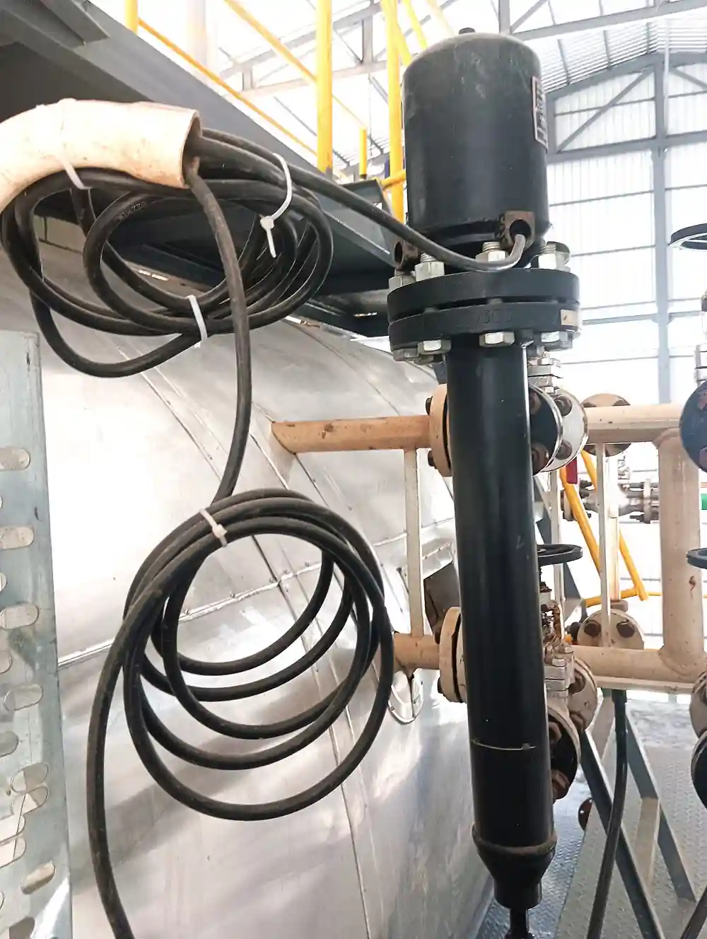
A tuning fork level switch is a point level detector: it answers one question at one elevation, is liquid present at this line or not, and it answers with a discrete electrical output. The sensing element is a pair of metal tines machined as one piece with a heavy root, driven into mechanical resonance by piezoelectric ceramics seated in that root. In gas the tines ring at their natural frequency. In liquid, the mass of fluid moving with the tines loads the resonator and damps it, the frequency steps down, and the electronics switch the output within a second. Because the detected condition is a resonance shift rather than a weak electrical property of the fluid, the switching point holds without recalibration, and that single fact drives most of the decisions on this page.
Procurement engineers meet these instruments as overfill alarms on solvent and fuel tanks, as low level cutoffs protecting a centrifugal pump from running dry, as high level stops on CIP skid vessels, and as empty detection on powder silos feeding mills and screw conveyors. The decision this page settles is narrow: which switch point belongs where, which fork construction reaches it, which density and viscosity ratings cover the liquid, and which certificate chain the jurisdiction and the trip logic demand. The answer lands as an RFQ line set, one function, one process connection, one wetted length, one output format, one approval package, and every chapter below feeds that line set so the alarm is bought, not improvised.
This page treats the tuning fork level switch as a purchasing object: how the vibrating fork converts immersion into a switching decision, what density and viscosity limits the physics imposes, which construction and approvals match which duty, and how failure modes, installation practice, and proof testing belong in the specification. It is written for engineers who issue purchase documents, not for readers who want a brochure summary.
Chapter 1 / 06
What a Tuning Fork Level Switch Is and What Is Being Decided
A tuning fork level switch is deliberately a low information instrument, and that is its virtue. It reports one bit, wet or dry, at the elevation where the tines sit, with repeatability measured in millimeters and latency under a second. It does not trend, it does not interpolate, and it cannot be retuned from the control room. What it does is hold a single switching decision against time, fouling, and electrical noise, which is exactly what an overfill alarm, a pump interlock, or a drain valve start needs. The purchase problem is therefore not sensitivity but trust: the device must still switch correctly after two years of coating, thermal cycling, and vibration, and the specification must force the supplier to prove that in advance.
The boundary against continuous instruments must be drawn first, because level is two purchases. A level transmitter reports the full band as a 4 to 20 mA signal and serves control loops, inventory, and trending. A level switch guards one line and serves alarms and interlocks. Mature plant practice deliberately splits the two functions across different measurement principles, so a hydrocarbon tank may carry a continuous instrument for inventory on one physics and an independent switch for the legal overfill alarm on another. The fork's entire role is the second function. Wherever a specification asks a fork to behave like a transmitter, or asks one fork to cover two elevations, the specification is wrong, not the instrument.
The instrument landscape around the fork is easy to state and easier to misread. On the point side sit float operated switches, the electromechanical family visible in the lead photograph, conductive probes, the RF admittance level switch, capacitance probes, and the vibratory fork of this page. On the continuous side sit the hydrostatic level transmitter reading the pressure column, the radar level meter and the guided wave radar level probe timing microwave energy, the ultrasonic level meter timing sound in open atmospheric vessels, the capacitance level transmitter tracking a dielectric profile, the magnetostrictive level transmitter following a float in a stilling cage, and the magnetic level gauge showing level locally through a flap chamber. Each of those instruments has its own page on this site. The comparisons between them belong in the selection chapter, and only there.
What is being decided at RFQ stage is a short list with long consequences. First the function: high point alarm, low point cutoff, or both, one fork per elevation. Second the geometry: compact threaded housing, flanged build, or tube extension, chosen against nozzle depth, vessel pressure, and where the liquid line actually sits. Third the envelope: minimum liquid density, viscosity, and temperature at the switching point, which gate the electronics option. Fourth the paperwork: hazardous area certification, overfill type approval where the stored liquid is regulated, and functional safety data where the output feeds a trip. Fifth the electrical interface into the control system, relay, transistor, or current loop. A datasheet that answers all five receives firm quotations; one that answers three receives a site visit.
Four approval families organize the datasheet. Performance data for process instrumentation is evaluated and reported against IEC 60770 practice, which is what makes switching point figures comparable between makers. Overfill protection on facilities storing water endangering substances in Germany carries a type approval under WHG section 63, examined by BAM or an appointed body, and the certificate names the liquid classes and density limits covered. North American acceptance rides on UL or cUL listing for the electrical and process ratings. Hazardous area versions are certified under the EN IEC 60079 series through ATEX and IECEx schemes, and electronics claimed for safety functions carry IEC 61508 assessment with published failure rates. A datasheet quoting none of these is a price tag, not a specification.
Chapter 2 / 06
How the Vibrating Fork Detects Liquid
The resonator is a single machined piece of stainless in almost all designs, a fork with two parallel tines and a heavy root, with two piezoelectric ceramics mounted in pockets in the root. One ceramic is the drive, excited by an oscillator; the other is the receiver, generating a signal from the tine motion and feeding it back to the drive. The loop self tunes: the assembly always rings at its mechanical resonance, the way a crystal oscillator tracks its quartz. In air the resonance sits in the low hundreds of hertz for the long tines used in liquid service, roughly 110 to 400 Hz depending on geometry and maker, with short compact tines running near 1,000 Hz. The resonance is sharp, with a high quality factor, and that sharpness is what makes the immersion signature clean enough to switch on in under a second.
Immersion changes two things at once. Liquid adjacent to a tine must accelerate with it, an added mass that pulls the resonant frequency down in proportion to liquid density, and viscous shear along the tine surfaces dissipates energy, damping the amplitude and forcing the drive to supply more current for the same motion. The frequency step in liquid is typically 10 to 25 percent of the air value, tens of hertz on a long tine, far outside any drift band. A switch electronics package can therefore detect liquid on a frequency threshold, on an amplitude or drive current threshold, or on both. Designs that credit both indications are the candidates for functional safety duty, because two independent signatures of one physical event make the failure mode analysis tractable. Wet to dry hysteresis is a few millimeters, catalog repeatability is typically plus or minus 2 mm in clean liquid, and detection latency is well under a second before any configured delay.
The configurable time delay, 0 to 30 seconds on most electronics, exists for surface motion. An agitated tank, a filling lance splashing near the fork, or a sloshing road tanker wets the tines transiently, and an interlock should not act on that. One to three seconds of delay is standard practice on stirred vessels and on suction drums that vortex. The trade is explicit: overfill alarms tolerate long filters because the level ramp is slow, while dry run protection for machinery wants the shortest honest delay the surface behavior allows. The delay belongs in the RFQ with its justification, not in a commissioning argument at two in the morning.
Density limits fall straight out of the physics. Both the frequency step and the damping scale with density, so light liquid produces a small signature. Standard liquid forks switch reliably down to 0.5 to 0.7 g/cm3; water, caustic, acids, and most oils sit far above that line. Light hydrocarbons such as LPG, pentane, and warm condensate near 0.5 g/cm3 need the extended density option, whose electronics resolve a smaller shift and whose certificate states the density at which switching was witnessed. In the opposite direction the same resonator can serve as a densitometer: permanently immersed, its frequency is a function of density, and density reading builds cover roughly the 0.5 to 2.0 g/cm3 band for concentration monitoring duties. Viscosity is the second envelope: viscous fluid damps the tines, frequency shift based designs tolerate up to about 10,000 mm2/s, amplitude based designs choke far earlier, and polymer or syrup service must be checked against the datasheet line, not assumed.
The output stage is where the fork meets the wiring diagram, and three formats cover the market. Electromechanical relay outputs, typically DPDT, switch starter circuits and legacy panels at mains voltage and a few amperes. Transistor outputs drive 24 V DC discrete inputs directly. The two wire current format suits safety wiring best: 8 mA dry, 16 mA wet, and a fault current below 2.5 mA on a failed piezo or broken conductor, so a current sensing input can distinguish all three states and no single fault imitates a healthy dry reading. Whatever format is chosen, the RFQ must state the fail direction on power loss and the fault signature, because the trip logic will be written against the wiring diagram, not against the brochure.
Chapter 3 / 06
Types, Construction, and Duty Boundaries
Catalog format follows installation economics. The compact housing is a one piece stainless body with a G 1-1/2 A or 1-1/2 NPT process thread, electronics in the same housing, aimed at small vessels, day tanks, skids, and pump protection lines, with process pressure typically to 40 bar. It screws into a nozzle or weld boss and, with the right certificate, into a hydraulic line. Flanged builds, DN25 to DN100, CL150 and CL300 standard with higher classes quoted as project specials, carry tank farm and chemical duty where thread sealing into a nozzle is unwelcome or where the wetted parts must be documented as part of the pressure boundary. Both formats share the same resonator physics; what changes is reach, rating, and paper.
Extensions carry the fork to the liquid line. Wetted lengths of roughly 100 to 250 mm suit most nozzle installations, and tube extensions span 80 mm to about 2 m, with 3 m as the practical ceiling for liquid service: the tube couples the resonator to the housing, shifts the resonance, derates the temperature rating, and loads the nozzle, all of which get worse as the tube grows. For bulk solids the same vibratory principle is scaled into a single rod sensor reaching about 4 m and rope suspended builds for tall silos to roughly 20 m, switching on the damping that settled powder applies to the rod. Those are empty detection and feed protection instruments with minimum bulk density limits on the order of 80 g/l for standard builds, and they are a different purchasing line from the liquid fork even when the catalog shares a page with them.
Wetted materials decide service life. 316L is the default for tines and body and covers water, hydrocarbon, and most chemical duty. ECTFE and PFA coatings buy compatibility in brines and acids where bare stainless would pit, and full Alloy C-276 bodies are quoted for aggressive chloride and acid service. Hygienic builds use electropolished 316L with surface finishes better than 0.8 micron Ra, clamp connections per ASME BPE, and crevice free tine geometry, documented for CIP cleaning and SIP sterilization cycles at 135 to 150 deg C. In every coated or alloy case the certificate, not the material name, is the purchasable item: coating permeation and crevice corrosion are chemistry questions the supplier must answer in writing against the actual process fluid.
Temperature and pressure envelopes follow the seals and the piezo stack. Standard compact forks work from minus 40 to plus 150 deg C process temperature. Thermal stand off extensions isolate the electronics from hot processes and extend service to 250 or 280 deg C on hot oil and steam condensate duty. Cryogenic variants for liquefied gases near minus 196 deg C exist as certified specials, and the RFQ should demand that certificate explicitly rather than assume the standard stack survives. Pressure follows the connection: threaded builds to about 40 bar, flanged builds take the flange class rating with its temperature derate, exactly as the flange standard tables do, and the datasheet must reproduce that derate rather than quote a single number.
The boundaries deserve blunt statements. One fork detects one elevation, and a specification that needs three answers buys three forks or a continuous instrument. A fork rated to 0.7 g/cm3 minimum density will not switch on 0.55 g/cm3 LPG no matter how it is wired. A fork mounted where the inlet jet impinges will nuisance trip on spray. A liquid fork geometry will bridge with fine powder. A fork in a nozzle whose bore swallows the tines detects the nozzle, not the vessel. The table below maps common duties to the construction that survives them and the construction that generates callbacks.
Service
Construction to specify
Construction to avoid
Solvent or fuel tank overfill alarm
Flanged DN40 or DN50, 316L, WHG type approval where in scope, SIL data, 8/16 mA output
Relay only housing with no fault reporting path
Pump dry-run protection on suction vessel or line
Side entry compact fork at the NPSH margin elevation, 1 to 3 s delay, de-energize to trip
Long top extension ending inside the vortex cone
LPG, pentane, warm condensate near 0.5 g/cm3
Extended density electronics certified at the service density
Thermal stand off extension with high temperature rating
Compact housing mounted directly at process temperature
Powder silo empty detection feeding a mill
Single rod sensor rated for bulk solids, rope build above 4 m
Liquid fork geometry installed in bulk powder
Chapter 4 / 06
Key Specification Parameters
The rows below decide whether a quoted instrument matches the service; the paragraphs after the tables say what a complete answer contains and what a weak one looks like.
Attribute
Typical range or options
What it decides
Process connection
G 1-1/2 A or 1-1/2 NPT; DN25 to DN100 flange; hygienic clamp
Pressure boundary, nozzle fit, and wetted parts documentation
Wetted length and extension
100 to 250 mm standard; 80 mm to 3 m tube; rod 4 m; rope 20 m
Whether the tines reach the true liquid line or the nozzle dead zone
Minimum liquid density
0.7 g/cm3 standard; 0.5 g/cm3 extended option
Switching certainty on light hydrocarbons at service temperature
Maximum viscosity
10,000 mm2/s on frequency shift designs
Damping margin in oil, polymer, and syrup service
Process temperature
minus 40 to 150 deg C standard; to 280 with stand off; cryogenic specials
Piezo stack, seals, and coating survival
Process pressure
40 bar threaded; flange class rating with derate
Body rating and the derate curve the datasheet must reproduce
Wetted materials
316L; ECTFE or PFA coated; Alloy C-276; electropolished hygienic
Corrosion envelope backed by certificates, not chemistry names
Output format
DPDT relay; PNP transistor; 8/16 mA two wire with fault current
Interface to the control system and the fail behavior on faults
Time delay
0 to 30 s configurable
Riding through slosh and splash without missing real events
Approvals
ATEX, IECEx, UL, cUL, WHG overfill, IEC 61508 SIL
The legal and safety paper the site audit will ask for
Several rows deserve prose. Density: the certified minimum must be stated at the process temperature, not at reference conditions, because hot light hydrocarbons are the exact case that fails silently between FAT and first summer. Extension: state the nozzle depth and let the supplier quote wetted length, but check the resonance and derate consequences of any tube past 2 m. Output: the two wire format's fault current is only useful if the input card is specified to discriminate it, so the RFQ names the input type the PLC provides. Delay: a number with the reason it exists, so commissioning does not zero it out under pressure. Approvals: certificate numbers, because a WHG approval covers named liquid classes and densities, an ATEX certificate covers named gas groups and temperature classes, and an SIL certificate covers a named architecture with a named proof test interval.
The package context matters at the IO level. A blanketed or pressurized vessel usually carries a pressure transmitter for blanket control and a continuous instrument for level, and the fork shares junction boxes, cable trays, and marshalling with both. State the package in the RFQ, vessel pressure transmitter tag, level instrument tags, and fork point tags, so the supplier scopes the IO correctly and the installer does not discover a full junction box during loop checks. The cause and effect drawing should show the fork alarm beside the continuous reading it cross checks, which is also how an auditor later reconstructs the layer of protection.
The format table compresses the geometry decision for specification meetings.
Fork format
Typical mounting
Duty it earns
Limit to check
Compact liquid fork
Threaded nozzle, skids, small vessels
Dry run and high level points to 40 bar
Density rating and viscosity at temperature
Flanged liquid fork
Storage tanks, process vessels
Overfill alarms carrying WHG or SIL paper
Flange class derate with temperature
Extended tube fork
Top of deep nozzles and domed heads
Reaching the liquid band below tall nozzles
3 m ceiling, resonance shift, nozzle load
Solids rod and rope
Silo roof, hopper outlet
Empty detection and mill feed protection
Minimum bulk density, about 80 g/l order
Density reading fork
Permanently immersed line
Density and concentration monitoring
Needs stable temperature or compensation
A weak quotation is easy to name: a single minimum density figure with no temperature attached, a SIL logo with no failure rates, an extension quoted without resonance or load comment, a relay contact with no fail direction stated, a time delay defaulted rather than specified. Each of those omissions is where the instrument later fails an audit or a claim, and each is a legitimate reject flag on the returned datasheet before price is even discussed.
Chapter 5 / 06
Selection Decision Factors and RFQ Language
The decision sequence is short enough to run as a checklist in a specification meeting, and each step eliminates a class of quotations before price comparisons begin.
Fix the function: one elevation, one answer. A fork is a level switch, not a continuous instrument; if the loop needs a band, buy a level transmitter for control and this level switch for the alarm line.
Write the liquid as it is: density at temperature, viscosity, solids, crystals, and foam tendency, because these gate the electronics and materials, not the brochure chemistry.
Confirm the density rating at service temperature, the silent failure case of hot light hydrocarbons.
Choose the format: compact thread for skids and pump lines, flange for tanks and aggressive service, extension only as deep as the nozzle forces.
Check the envelope: temperature and pressure with derates, including cleaning and sterilization cycles where they exist.
Select materials and coatings with certificates: 316L default, coatings or Alloy C-276 where chemistry demands, electropolished builds for hygienic duty.
Fix the output, fail direction, and delay against the wiring diagram and the surface behavior of the vessel.
Demand the paper: ATEX or IECEx per zone, WHG or UL as the jurisdiction requires, SIL data where the fork feeds a trip, and a witnessed wet functional test at FAT.
Against the neighboring point technologies, the honest comparison runs as follows, and it belongs here rather than anywhere earlier. Float switches are the incumbent: cheap, simple, and proven in clean water, but they carry hinges, pins, and magnet mechanisms that scum and scale eventually bind, and a stuck float is a silent alarm. The RF admittance level switch reads the electrical admittance between a probe and the vessel wall; it must be calibrated against the dielectric behavior of the actual liquid, it drifts when composition changes, and conductive coating on the probe reads as liquid that is not there. The capacitance level transmitter runs the same physics continuously and inherits the same buildup sensitivity. The vibrating fork asks nothing of the fluid but density: no dielectric constant, no conductivity, no calibration against composition, and light dry buildup does not cross its threshold. That is the whole of the argument for forks in dirty hydrocarbon, chemical, and coating prone service. Where the question is continuous level rather than a line, the fork has no answer: that purchase belongs to the hydrostatic level transmitter, the radar level meter, the guided wave radar level probe, or the ultrasonic level meter, and precision inventory in a stilling cage belongs to a magnetostrictive level transmitter usually paired with a magnetic level gauge for local reading.
Dry run protection is the duty where the fork most often displaces a flow switch, and the reasoning is worth writing into the specification. A discharge mounted flow switch reports zero flow whenever anything blocks the path, so a closed suction valve nuisance trips a healthy pump start, and the flow switch knows nothing about the inventory the pump will actually draw on. A fork on the suction vessel or line, mounted at the elevation where NPSH margin ends, measures that inventory directly and trips only when running the centrifugal pump is genuinely unsafe. On volatile service mount it at the NPSH line rather than the vessel bottom, where a pickup vortex unmakes the reading seconds before the level truly ends. Wire the trip de-energized to act, and prove it with liquid, never with a simulator.
The application map turns the reasoning into a table the project file can carry.
Application
Construction to specify
Check before order
Flammable solvent tank overfill alarm
Flanged DN40 or DN50 fork, 316L, SIL data, WHG approval where in scope, ATEX certificate
Certificate density against the actual liquid; cause and effect cross checked against the tank level transmitter and pressure transmitter tags
Boiler feed pump protection on a deaerator or suction drum
Side entry compact fork at the NPSH margin elevation, 1 to 3 s delay, de-energize to trip
Vortex and swirl pattern at low level; documented interlock test procedure
Caustic or acid day tank high level
Coated tines or Alloy C-276 body, flanged connection
Coating permeation and temperature limit in writing
SIP temperature certificate and surface finish report
LPG sphere or bullet high level
Extended density fork, CL300 flange, stainless wetted parts
Minimum density certificate at working temperature
Powder silo empty detection feeding a mill
Rod or rope vibratory sensor rated for bulk solids
Bulk density at handling conditions; aeration behavior of the powder
The RFQ block should be written once and reused. A complete block reads: quantity and function per point; setpoint elevation against vessel datum; process connection size and rating; wetted length or extension; minimum certified density at process temperature; viscosity; process, ambient, and cleaning temperatures; design pressure with derates; wetted materials and coatings with certificates; output format with fail direction, fault current, and contact rating; time delay with justification; hazardous area certificate with gas group and temperature class; WHG overfill type approval or UL listing where the jurisdiction demands it; SIL data with PFDavg, architecture constraints, and proof test interval; and acceptance as a witnessed wet functional test at FAT using a liquid of certified density, plus a fault simulation at the terminals. A quotation returned without the density certificate, the fail direction, or the SIL data is incomplete at any price.
Chapter 6 / 06
Installation, Standards, Failure Modes, and Maintenance
Installation quality decides whether the fork reaches its catalog life. Set the nozzle depth so the tines clear the bore and any weld root, because a fork recessed in its nozzle detects the nozzle. Side entry at the exact alarm elevation is the geometry of choice for limit points on drums and day tanks; top entry suits tall vessels where the extension economics work. Keep the tines at least 50 mm clear of walls, ladders, coils, and agitator paddles, and keep them out of the inlet jet: where the layout is fixed, a baffle plate between inlet and fork costs less than a year of nuisance trips. Housing orientation is largely free, but mount the cable entry downward with a drip loop so gland leakage cannot find the terminal block.
Commissioning practice proves the point, not the pixels. Raise liquid through the fork elevation with water or process fluid and record the level switch trip point against the mechanical datum, then verify the fail direction by removing power and the fault signature by disconnecting one conductor at the marshalling strip. Confirm the trip lands in the PLC and in the relay panel, both, not one. Set the delay against the real surface behavior, watch a fill and a drain cycle if the process allows, and file the record as the baseline for every proof test that follows. A fork that trips correctly once, at the right level, with the right fail direction, has earned its certificate chain; anything less is an assumption wearing a loop check sticker.
The standards set the verification frame. Performance data is evaluated and reported against IEC 60770 practice, which is what makes datasheet figures comparable. Overfill type approval under WHG section 63, examined by BAM or an appointed body, is the German legal requirement for facilities storing water endangering substances, and the certificate scope is the deliverable, not the logo. UL and cUL listings carry North American electrical acceptance. ATEX and IECEx certification per the EN IEC 60079 series covers hazardous area installation, zone, gas group, and temperature class. IEC 61508 assessment, with failure rates and proof test basis, covers any output that feeds a safety function. Flanged housings inherit the flange standard ratings, ASME B16.5 or EN 1092, with their full derate tables. Citing these by name in the RFQ moves the burden of proof to the supplier, which is where it belongs.
Failure modes in service follow a short and predictable list. Buildup bridging: sticky or crystallizing solids span the gap between the tines, damp the resonator, and hold a false wet signal; flush connections and crest free tine geometry are the countermeasures, and a false wet that survives a solvent flush is a mechanical inspection ticket. Erosion: slurry and catalyst fines thin the tines over months, the air resonance drifts until the electronics complain, and thinned tines crack at the root; inspect at every turnaround in abrasive duty. Corrosion fatigue: chlorides above roughly 60 deg C attack 316L tine roots, stress cycling does the rest, and the failure arrives as a frequency alarm or a lost resonance; specify Alloy C-276 wetted parts in warm chloride service instead of learning this. Electronics and piezo faults are self diagnosed to the fault current, which is exactly why the input card must be able to see it. Gland water ingress corrodes terminals and mimics every other fault; freezing condensate on outdoor vent lines damps tines seasonally; and long field runs pick up surge damage that terminals protection would have absorbed.
Maintenance scales with the SIL claim, not with sentiment. The proof test interval comes from the loop calculation, commonly 12 months for a SIL 2 single fork, and the test is a wet functional check with the result recorded against the baseline from commissioning. Every plant shutdown earns a visual tine inspection for erosion, cracking, and coating holidays. Trend the alarms a fork generates against the vessel's continuous instruments: a fork that repeatedly disagrees with the level transmitter or the magnetic level gauge is reporting that one of the two is wrong, and settling that question before the next batch is far cheaper than after it. Keep the certificate dossier current, because an overfill approval that expired with a firmware change is an audit finding waiting for its date.
FAQ
What is the minimum liquid density a vibrating fork can switch on?
Most standard liquid forks carry a certified minimum density of 0.5 to 0.7 g/cm3, set by how much damping and frequency shift the liquid imposes on the tines. Water, caustic, and most oils sit far above the limit. Light services such as LPG, naphtha, pentane, and warm condensate demand the extended density option, rated near 0.5 g/cm3 or lower, and the certified density figure must appear on the datasheet at process temperature, not at reference conditions.
Will foam or vapor falsely trip the fork?
Open foam with low liquid content damps the tines too little to cross the switching threshold, so agitated solvent tanks with foam heads usually stay free of false wet alarms. Vapor, mist, and condensing droplets in the headspace are ignored for the same reason: negligible moving mass. Dense, wet froth can trip a fork, and that behavior is either exploited deliberately in flotation service or filtered out with a time delay of a few seconds.
How does buildup on the tines affect switching?
Thin, dry, or non-sticky films on the tines shift the air resonance slightly and rarely cause a false wet signal, which is the basis of the fork's reputation in fouling service. Sticky, conductive, or crystallizing buildup that bridges the gap between the tines acts like liquid and produces a permanent wet indication. Flushing connections, coated tines, and crest free tine geometry are the specified countermeasures in crystallizing duty.
Which approvals does an overfill protection switch need?
For water endangering liquids stored in Germany, the switch needs a type approval under WHG section 63, examined by BAM or an appointed body, and the approval certificate names the liquid classes and densities covered. North American sites generally require a UL or cUL listing for the electrical and process rating. Hazardous areas add ATEX or IECEx certification for the zone and gas group, and SIL rated loops add an IEC 61508 certificate with PFDavg and proof test interval.
Can a tuning fork protect a pump from dry running?
Yes, this is one of the two classic duties. Mount the fork low on the suction vessel or line, at the elevation where the centrifugal pump still has adequate NPSH margin, wire the switch into the pump interlock with fail safe wiring, and set a delay of one to three seconds to ride through surface swirl. The fork measures available liquid directly, which a discharge side instrument cannot do when the suction valve is closed.
What output should I order for a trip input?
Order the two wire current variant for safety related wiring: 8 mA dry, 16 mA wet, and a fault current below 2.5 mA on a broken piezo or lead, so a PLC input can discriminate all three states and no single fault imitates a healthy dry reading. Relays suit starter circuits and legacy panels, and transistor outputs suit conventional 24 V DC discrete inputs. State the fail direction in the RFQ.
How often must a SIL rated fork be proof tested?
The proof test interval comes from the SIL calculation, not from habit: the certificate supplies PFDavg, and the loop owner combines dangerous undetected failure rate with trip frequency to set the interval, commonly 12 months for SIL 2 loops and sometimes three to five years where the calculation supports it. The test itself is a wet functional check, raising level to the fork and confirming the trip in the control system, recorded with date and result.