AECs are copper cables with embedded electronics that extend rack-scale interconnects beyond the distance limit of passive direct-attach copper (DAC), while staying below the power and cost envelope of active optical cables (AOCs) [S3]. They sit in the same physical form factor as DACs (QSFP-DD, OSFP, OSFP224) but add linear or DSP-based equalization inside the plug to preserve signal integrity at higher per-lane speeds.
For AI rack builders, AECs matter because GPU-to-GPU scale-up fabrics, including UALink, NVLink, and proprietary topologies, are now standardising on 200G/lane and 400G/lane PAM4 signalling, where passive copper rolls off quickly past 1.5 m [S3][S1]. The reference product set spans 800G and 1.6T (1.60T) AEC assemblies from Credo, Molex, Marvell, and Amphenol, all targeting in-rack and adjacent-rack scale-up links [S1][S2][S3][S6].
AEC vs ACC vs AOC vs DAC: where each copper/fibre class fits
DAC, ACC, AEC, and AOC are not interchangeable; they segment cleanly by reach, per-cable power, and the type of signal conditioning used [S3]. Passive DAC is the cheapest, lowest-power option but loses signal integrity past roughly 2 m at 200G/lane, which is why active variants have emerged [S7].
Active Copper Cable (ACC) is the newest category, announced as a product class in late 2025, and is aimed at 2.0–2.5 m links inside a single rack [S3]. A 1.6T ACC typically draws about 2.5 W, uses an analog linear equalizer (e.g. Marvell CB11208 providing up to 20 dB of equalization), and relies partly on the host switch to absorb the remaining channel loss (a 32 AWG ACC can exhibit up to 45 dB of loss) [S3]. AECs add a DSP at each end for stronger signal correction, which increases reach and tolerance but also raises power and latency relative to ACC [S3]. AOCs push the farthest (up to about 30 m) by combining DSPs, transimpedance amplifiers, and drivers with optical fibre, at a higher per-cable power budget [S3].
The headline figure from a Marvell/Infraeo demonstration is a 9 m AEC operating at 800G, which is long enough to span roughly seven racks and approach a full row in a typical AI training hall [S3].
Electrical and Mechanical Specs That Drive AEC Selection
AI rack builders should size an AEC on four concrete parameters: per-lane signalling rate, total bandwidth, reach, and per-cable power, with form factor and latency as secondary constraints [S2][S3]. Molex's AEC product line is specified to deliver data rates up to 1.60Tbps and is positioned to scale with AI infrastructure performance requirements [S2].
Typical AEC product families in 2026 span 400G (4×100G), 800G (4×200G or 8×100G), and 1.6T (8×200G) variants in OSFP, QSFP-DD, and OSFP224 packages, with 1.6T OSFP224 XDR AEC and DAC assemblies now shipping as standard catalog SKUs [S4]. Credo's ZeroFlap AEC portfolio is built around 224 Gbps per lane PAM4 SerDes IP, which is the generation that feeds 1.6T end-to-end links [S1].
Rack-level AEC density is non-trivial: each rack can accommodate up to 500 cables in dense CLOS or Distributed Disaggregated Chassis (DDC) topologies, which is why hyperscalers treat per-cable wattage and per-cable cost as fleet-scale numbers, not component-scale numbers [S4][S3]. Power and density considerations are part of broader industrial power architecture planning, where the rack's DC power supply and switching power supply rails must be sized for hundreds of active cable endpoints.
Where AECs Land vs. Where They Don't
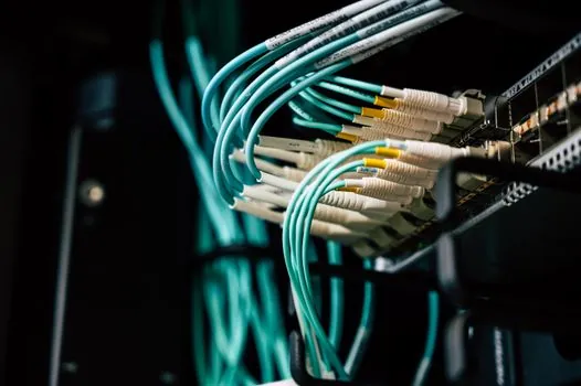
AECs are for builders wiring GPU-to-GPU scale-up fabrics and high-radix ToR-to-spine links inside a single row, especially when 200G/lane or 400G/lane signalling pushes passive DAC past its useful reach [S3][S5]. They are also a fit when operators want telemetry on link health, because AEC and AOC platforms increasingly ship with built-in predictive monitoring of signal integrity, temperature, and BER [S6].
AECs are not a fit for sub-1 m, low-cost leaf patching (passive DAC still wins on cost and power) and not a fit for cross-row, cross-aisle, or building-scale runs above roughly 30 m, where AOCs or optical transceivers on fibre are the correct choice [S3]. They are also not a fit when a customer needs zero-latency budget for the cable itself: ACC is lower-latency than AEC, and AEC is lower-latency than AOC, so latency-sensitive scale-up designs may still prefer ACC inside the rack [S3].
Selection Criteria and a Decision Rule
A practical specification rule: choose passive DAC for sub-1.5 m, low-cost 100G/lane or 200G/lane links; choose ACC for 2.0–2.5 m same-rack scale-up links where power and cost are tightly constrained (≈2.5 W per 1.6T cable); choose AEC for 3–9 m cross-rack scale-up links where DSP-based signal correction is needed; and choose AOC for everything above that, up to about 30 m [S3][S7]. This decision sits inside the broader electrical automation and industrial UPS planning that any AI hall must lock down before cabling pulls begin, and it is also why electrical measurement of per-port BER and eye height is now a routine rack-acceptance step.
Verification of cable health is increasingly done in-cable, not just at the switch: Amphenol's AEC product family embeds telemetry and analytics directly in the cable assembly to support predictive maintenance on GPU-scale infrastructure [S6]. The benefit is that a 500-cable rack, where manual swap-and-test is impractical, can be monitored link-by-link before soft errors degrade a training job.
Standards, Topology, and Fleet-Scale Considerations
AECs are deployed inside the rack and across adjacent racks using standard pluggable form factors (QSFP-DD, OSFP, OSFP224), so they ride the same mechanical and EEPROM ecosystem as DACs and AOCs and can be swapped at the port level [S4]. The architectural driver is the move toward CLOS switch rack or Distributed Disaggregated Chassis (DDC) topologies powered by 25.6Tbps switch silicon, where copper above the server access layer is the preferred medium for short, dense links [S1].
At fleet scale, the small per-cable power differences (a few watts) compound into megawatts once a hyperscaler deploys millions of links, which is why ACC, AEC, and AOC will coexist rather than one displacing the others [S3]. A 1.6T ACC at ≈2.5 W is roughly an order of magnitude lower than a typical 1.6T optical transceiver, which is the main reason copper is being pushed deeper into the AI fabric than it ever was in the 100G era [S3][S2].
Failure Modes and Engineering Watch-Items
The dominant AEC failure modes are link flaps from marginal equalization at the long end of the cable's reach budget, thermal stress on the plug assembly in hot-aisle containment, and firmware/EEPROM mismatches when a newer switch tries to read an older cable's diagnostics page [S1][S3]. Credo's "ZeroFlap" AEC portfolio is explicitly positioned around eliminating soft link flaps that hurt cluster reliability, which is a real, named fleet-scale failure mode rather than a marketing term [S1].
Two engineering watch-items are worth tracking: ACC's reliance on host-switch equalization (if the switch only delivers 10 dB of compensation, the 32 AWG ACC's 45 dB loss budget is not closed) and AEC's higher latency relative to ACC, which matters for tight scale-up collectives where the all-reduce step is latency-bound [S3].
Trackable next signals: (a) the ramp of 200G/lane and 400G/lane PAM4 switch silicon shipping with built-in ACC-grade equalization, which will determine how thin the line between ACC and AEC becomes; and (b) whether the 9 m / 800G AEC demonstration point generalizes to 1.6T AEC at the same reach, which would push copper deeper into cross-rack scale-up than today's [S3]. Operators planning AI halls in 2026 should also see how copper-heavy designs interact with broader electrical automation layouts, since every watt saved in the cable budget is a watt the DC power supply and industrial UPS do not have to deliver.
For related coverage, see Additive Manufacturing Qualification Data Package for Production Parts.