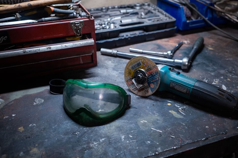
Correct angle grinder disc installation is a six-step sequence — isolate power, lock spindle, mate backing flange to disc bore, thread outer flange, verify runout, set guard — and the same sequence applies to 100 mm, 115 mm and 125 mm class machines because the M14 spindle (or 5/8-11 UNC on North American 115/125 mm models) is the de-facto mounting interface across the category [S3].
This guide is written for shop-floor users, maintenance technicians and OEM service writers who need a single procedure that covers Type 27 (depressed-centre) cutting and grinding wheels, Type 42 (flat) cutting wheels, flap discs and wire/cup brushes on a angle grinder body. Two design features determine whether the procedure is fast and safe: a gear-case spindle lock to hold the shaft during nut run-down [S3], and an anti-locking flange pair that prevents the operator from over-torquing the wheel onto the spindle [S3]. Where either feature is missing or worn, the procedure degrades into a wrench-on-the-flange improvisation that cracks discs.
Pre-Install Gates: Disc Rating, Guard Angle, PPE
Before any disc touches the spindle, three checks fail the job if they do not pass. First, the disc's rated maximum operating speed (in m/s or rpm) must exceed the grinder's no-load speed by a margin — Type 27 125 mm cutting discs from UAE aftermarket channels are typically marked 80 m/s, which exceeds the ~72 m/s no-load rim speed of a 11000 rpm 125 mm machine [S4]. Second, the wheel guard must be rotated to the operator side and clamped; on most 115/125 mm grinders the guard collar sits on a detent ring with 7-12 indexed positions, and the chosen position must clear the work-piece and the user's leading hand. Third, the operator must wear ANSI Z87.1 (or EN 166) impact-rated eye protection, an FFP2/FFP3 or N95 dust mask for masonry cutting, leather gloves, and a face shield for 125 mm cut-off work.
Power-side gating: corded 230 V machines get a residual-current device (RCD, 30 mA) on the supply; 18 V/20 V cordless angle grinders use a battery pack with a state-of-charge indicator that the operator reads before starting — a 4.0 Ah pack at 25 % state-of-charge will not sustain a 125 mm metal-cut cycle and risks low-voltage cut-out mid-cut. For abrasive selection, the disc diameter, bore (22.23 mm for European 100/115/125 mm; 7/8 in / 22.2 mm for North American), thickness and abrasive specification must all match the spindle, the guard's max-wheel marking, and the workpiece material [S4].
Spindle Lock, Flange Pair and Nut Torque
The spindle-lock button is a spring-loaded pin that engages a detent in the gear-case end of the output shaft. Pressing the lock while rotating the spindle by hand seats the pin in the detent; on worn machines the operator feels a slight click rather than a hard stop, and the lock must be re-seated before applying flange torque [S3]. With the spindle locked, the inner backing flange (a flat disc with a register that matches the wheel bore) is placed against the spindle shoulder, the abrasive disc is slid over the spindle and seated flat against the inner flange, and the outer threaded flange is hand-threaded onto the M14 × 2 spindle (or 5/8-11 UNC).
The outer flange is the anti-locking component: it is designed to slip against the wheel under excessive torque, which is why a plain spanner on the outer flange will not achieve the correct clamp load [S3]. A pin spanner engaged in the holes of the outer flange, or a two-pin spanner on a cast spanner ring, is the correct tool. Torque target on the outer flange is approximately 8-12 N·m for a 115/125 mm Type 27 grinding disc — enough to prevent wheel slip, not enough to clamp the wheel into a pre-load that fractures it on first cut. After the nut is tight, the spindle lock is released, the spindle is rotated by hand through one full revolution, and any rubbing, binding or out-of-plane wobble is addressed before power-on.
Disc Type vs Application Map
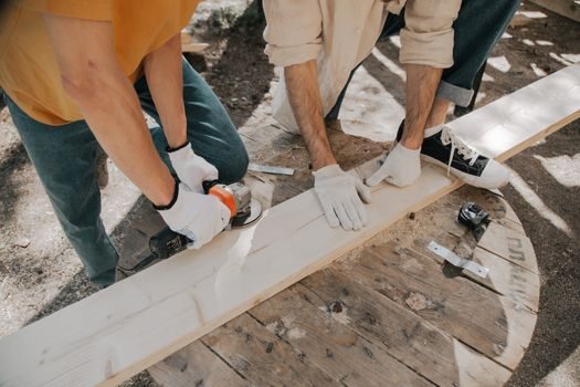
Five disc families cover ~95 % of angle-grinder work, and each has a different installation nuance. Type 27 depressed-centre grinding wheels (4-7 mm thick) are clamped between flanges with the depression facing the guard; Type 27 cutting wheels (1.0-3.0 mm thick) use the same orientation but require a cutting guard (closed on the operator side). Type 42 flat cut-off wheels (1.0-3.0 mm) are clamped in a flat orientation, both flanges flat against the disc, and must run in a closed cutting guard, never a grinding guard. Flap discs (Type 27 backing with abrasive flaps) clamp like a grinding wheel but do not need the same level of flatness check — a 5° tilt is acceptable on the backing face. Wire cup brushes and wire wheels mount directly to the M14 spindle without the outer flange, and the spindle lock is held while the brush is hand-screwed on; the brush's max-rpm marking must exceed the grinder's no-load rpm. [S1]
Buy-out rule of thumb: if a disc has been on a yard shelf for more than 18 months, drop-test it (light tap, no ring → reject) and re-rate its operating speed assumption. For a fettling grinder — the heavier, slower-rpm (≤6500 rpm) cousin used in foundry and forge work — the procedure is identical, but the higher torque and lower rim speed mean 7 mm Type 27 wheels and 4 mm Type 42 cut-off wheels are the only sensible abrasive choices; thinner discs shatter on a stall.
Guard, Side Handle and Auxiliary Controls
Three auxiliary features get checked while the spindle is locked. The wheel guard must be re-clamped to the operator side after every disc change, with the guard lip no more than 6 mm from the disc periphery at its closest point — a larger gap lets a shattered disc fragment travel past the guard, defeating its purpose. The side handle (M8 or M10 thread on European 115/125 mm bodies, 3/8-16 or 1/2-13 on North American) is mandatory two-handed operation: most jurisdictions make it a regulatory requirement under EN 60745-1 / IEC 60745 hand-held power tool safety. The handle mounts on the gear-case left or right side depending on cut orientation; some OEM bodies (Black & Decker EP1728591 family) use a vibration-damped handle with a soft-mount collar to drop handle-transmitted vibration below the 2.5 m/s² A(8) exposure threshold over an 8-hour day [S3].
Trigger and lock-on: a Black & Decker-style trigger assembly (per EP1728591A2) separates a first-position trigger (spring return, no lock) from a second-position trigger with a lock-on slide; only the second position is lockable, and the lock is mechanically disengaged by a separate user control, not by spring force [S3]. For a floor grinder — a different machine class on a vertical shaft with larger diamond or abrasive discs — the lock-on feature and the spindle-lock work the same way, but the procedure scales up to 180-230 mm discs, 5/8-11 or M20 spindles, and a multi-position guard that can be set for edge work.
Installation of Battery, Brushes and Dust Extraction

For cordless machines, the battery pack is the last item attached — a 18 V/20 V slide-on pack with a 4-5 Ah rating is typical for 115/125 mm work, a 9-12 Ah pack runs 180 mm wheels but adds 0.7-1.0 kg of hanging mass at the heel of the grip. Slide-on packs must be seated until the latch clicks; an unseated pack can drop out under vibration. For corded machines, the carbon-brush caps on the gear-case end of the motor are accessible without opening the case; brushes under 6 mm of remaining length (or below the manufacturer's wear-line) get replaced as a pair before commissioning [S3].
Dust extraction: a 35 mm or 50 mm OD cuff on the guard body is the common interface. For masonry cutting, the grinder is paired with an M-class (EN 60335-2-69) dust extractor with auto-start; the guard's extraction shroud must be the right diameter for the disc (open shrouds for 115 mm, closed shrouds for 125 mm), and a missing or torn brush ring at the cuff interface drops extraction efficiency below 50 % and pushes operator silica exposure above the 0.025 mg/m³ (8 h TWA) threshold used in EU jurisdictions. The particle evacuation fan inside the gear-case (per the EP1728591A2 patent family) is the OEM's last line of defence — it keeps dust out of the motor brushes, not out of the operator's breathing zone [S3].
Verification Before First Cut
A 60-second bench run after every disc change catches installation faults before they become injury events. Step one: dry-run the grinder at no-load for 30 s, listening for bearing rumble, brush chatter, or flange contact against the guard. Step two: verify runout — the disc face must not wobble by more than 0.1 mm at the periphery (visual check against a fixed pointer; on production lines, a dial indicator). Step three: confirm the wheel guard, side handle, and (on corded) RCD are all in place. Step four: for cut-off work, fit a closed cutting guard; for grinding, an open grinding guard; for flap or wire work, the guard as supplied for that application. [S2]
If the dry run is clean, the operator makes a 2-3 second test cut on a scrap piece at the lightest feed that produces sparks. A disc that stalls, chatters, or throws sparks asymmetrically is removed and re-checked. For related rotary hammer chuck work, the same discipline — lock, seat, verify runout, dry-run, test-cut — applies, although the spindle interface (SDS-Plus, SDS-Max) is a different mechanical system. Where the work involves abrasive or saw cut-off adjacent to a sealing washer interface, see the sealing washer four-gate spec map for the washer selection logic.
Common Installation Errors and Failure Modes
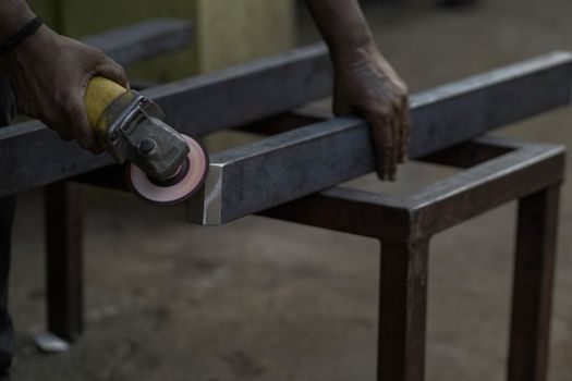
Four errors account for most disc-change incidents. Error one: a missing backing flange, or a backing flange from a different machine family with a different register diameter, which causes the disc to sit off-plane and shatter on first contact. Error two: an over-tightened outer flange that pre-loads the disc and cracks it within the first 10 s of cutting; the anti-locking flange is a slip-clutch, not a high-torque clamp [S3]. Error three: a guard set on the wrong side — the operator is downstream of the disc plane rather than behind the guard, so a fragment travels toward the face and torso instead of the floor. Error four: a Type 27 disc mounted in a Type 42 (flat) orientation, or a Type 42 mounted on a grinding guard that does not enclose the periphery.
Disc-life failure modes beyond installation: resin-bonded abrasive discs lose strength above 80 °C, so continuous cuts in mild steel without a 5-10 second cooling pause burn the disc; aluminium cutting at high feed loads the disc with soft metal that smears and re-cuts the abrasive; masonry discs loaded with wet slurry lose rigidity. A crossed-roller guide table is the wrong tool for an angle grinder — the categories are unrelated — but the same fail-fast logic applies: a noisy or rough-running axis is removed, not run harder. For shop hygiene adjacent to a linear guide installation, dust from cut-off work is a contamination source and the grinder should be kept on a separate bench with its own dust extraction.
Signals Worth Tracking Through 2026
Three signals are worth watching over the second half of 2026. First, cordless adoption in 115/125 mm class — 18 V/20 V brushless machines are crossing parity with 1000-1100 W corded on cut performance, which is shifting disc-change discipline into a battery-first workflow. Second, EU market-surveillance enforcement of EN 60745-2-3 on vibration and dust: grinders shipped after the latest regulatory cycle must publish a vibration A(8) value per handle, and aftermarket guards must declare compatibility per disc diameter. Third, abrasive-bond chemistry — the shift from phenolic resin to vitrified and hybrid bonds on 1.0-1.6 mm cut-off wheels extends disc life and reduces shatter risk, but changes the over-speed-failure mode from resin burn to bond fracture. [S3]
Trackable next nodes: the 2026 EN 60745-2-3 amendment for dust-extraction shrouds; the IECEx/ATEX certification status of any grinder specified for zone 1/zone 2 (paint shops, refineries); and the introduction of 76 mm (3 in) die-grinder-format angle heads that share the M14 spindle but with a smaller guard. For broader abrasive-process context, the sandblasting cost guide and the forging press selection guide cover two adjacent surface-preparation workflows that angle-grinder users frequently cross over into.