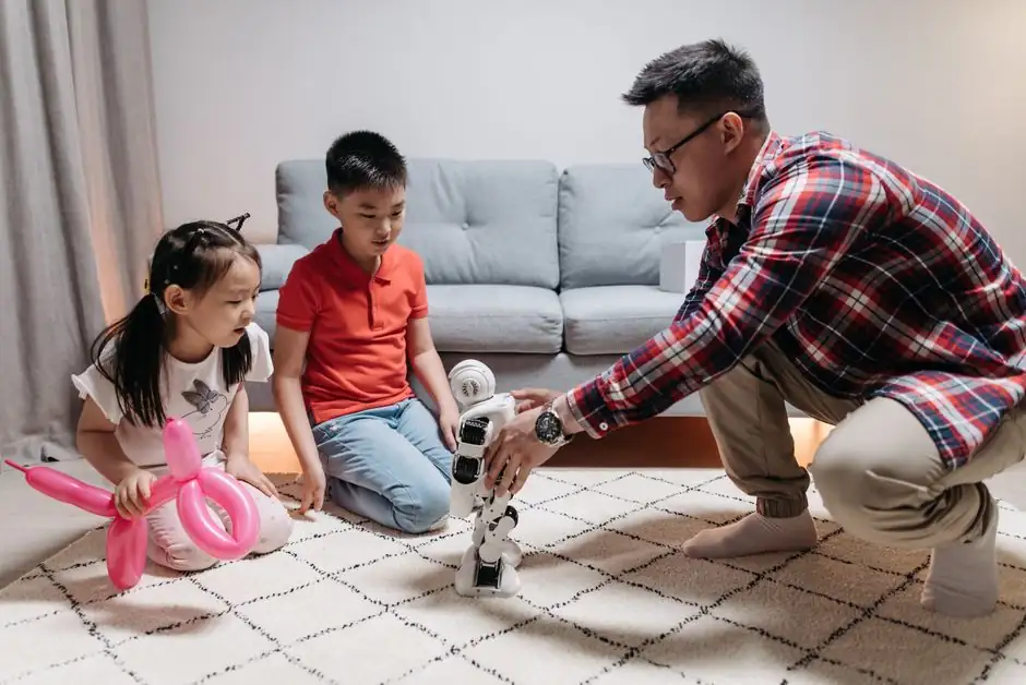
Install a typical 6-axis articulated robot through six controlled stages: foundation verification, mechanical mounting, utility connection, controller integration, axis commissioning, and production validation.
The scope covers robot arms, end effectors, controllers, safety systems, and operating procedures for welding, assembly, painting, and material handling [S1][S4].
Define the installation scope and mechanical class
Articulated robots are characterized by multiple rotary joints, also known as revolute joints [S4]. A 6-axis arrangement is appropriate when the task requires substantial reach, wrist orientation, and controlled positioning in welding, assembly, painting, or material handling [S1][S4].
Choose the robot model from the required payload, reach, axis count, repeatability, tool mass, work envelope, and process duty. For comparison, SCARA robots suit compact, selective motions, while articulated robots provide a larger working envelope and flexible wrist configuration for industrial processes [S4].
Install an articulated arm when the process needs multi-axis reach or wrist reorientation. Do not select it merely because a robot is flexible; if the work is a simple planar transfer, a fixed-payload handling system may be simpler. A dedicated collaborative robot should be considered when the application, tooling, risk assessment, and operating method support collaborative operation, because collaborative capability does not remove the need for safeguarding [S4].
Prepare the foundation and mounting interface
Start with the exact model manual, not a generic installation checklist. The Kawasaki BA013 Installation and Connection Manual applies to BA013, BA013N, and BA013L arms and covers the robot arm only; controller installation and arc-welding connections require separate manuals [S2].
Verify the foundation geometry, anchor positions, surface condition, load capacity, and vibration isolation against the model-specific drawing before drilling. The mounting base must transfer the static robot load, tool load, dynamic forces, and emergency-stop reaction into the foundation without uncontrolled movement. Install anchors only after checking the prescribed hole pattern, edge distances, embedment, grout or shim arrangement, and fastener torque in the manufacturer documentation [S2].
Keep the installation package traceable. For site handover, record the serial identification, anchor hardware, utility connections, controller version, end-effector configuration, and as-built photographs.
Set the robot, controller, and utilities
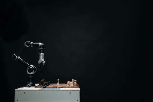
Position the robot and controller so the arm cannot strike the enclosure, guards, conveyor, or service access route during its specified envelope. Maintain the clearances and service zones defined by the selected model documents. ABB identifies articulated robots for welding, assembly, painting, and material handling, so the installation geometry must support the actual process rather than a generic maximum reach [S1].
Connect the arm and controller using the specified cables, connectors, and model-matched procedures. Kawasaki separates arm installation from controller installation, which prevents technicians from treating connector pin assignments or controller accessories as interchangeable across robot families [S2]. Check electrical supply, protective bonding, pneumatic or hydraulic service connections where fitted, and data cables before closing the cabinet. Do not energize a field device until conductor identity, connection destination, and mechanical restraint have been independently verified.
Use the motion controller installation guide only as a supporting reference for control-system commissioning. The controlling document remains the robot manufacturer’s installation and safety manual, because the robot controller also governs axis motion, limits, fault handling, and operating state [S2].
Commission each axis without production motion
Restore the robot in a controlled sequence: mechanical checks first, electrical checks second, controller checks third, and manual movement fourth. Kawasaki defines DANGER for actions that can cause imminent injury or death, WARNING for possible injury or death, and CAUTION for precautions covering specification, handling, teaching, operation, and maintenance [S2].
With the work area clear and emergency stops functional, power the system and inspect faults before enabling motion. Identify each axis, confirm its displayed direction and travel, and verify that mechanical stops, software limits, brakes, and the selected operating mode agree with the model specification [S2]. Move one axis at a time at reduced speed and begin at a posture that avoids abrupt gravity loads. The acceptance condition is not merely that the axis turns, but that it travels in the intended direction, stops predictably, holds position, and produces no abnormal noise, heat, vibration, or fault indication.
Do not bypass a limit switch, disable a brake, or force an axis against an obstruction to prove a fault. Replace or escalate when an axis moves beyond its intended range, loses repeatability, overheats, or repeatedly faults. Keep personnel trained for activation, teaching, maintenance, and inspection, as required by the manufacturer guidance [S2].
Validate the end effector and process path
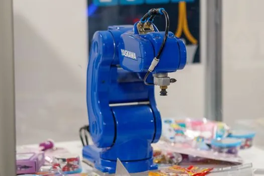
Install tooling only after its mass, center of gravity, orientation, cable routing, and fastener security have been checked against the robot and process requirements. The tool becomes part of the moving mass, so a gripper, welding torch, or other end-of-arm tool must be specified for the task rather than attached as an afterthought [S4].
Verify the complete programmed path at reduced speed, then test approach, retreat, part-present, and emergency-stop conditions. For welding, include torch clearance, fume extraction, gas service, and shielding requirements. For painting, verify material supply, recovery, static control where required, and the intended surface distance. For material handling, confirm grip, release, load retention, and collision clearance. ABB explicitly includes all four application families among articulated-robot uses [S1].
Validate accuracy where the process demands it. Establish acceptance criteria from the equipment specification and process capability, including positional deviation, cycle time, tool retention, and safe stop response. If the robot cannot repeat the qualified path, the fault belongs to mechanical installation, tool setup, program, calibration, or process conditions. Repair the identified cause before increasing speed or releasing the cell for production.
Resolve common installation faults by symptom
A robot that will not enable the motors requires a cause-based check of power availability, controller status, fault logs, and the manufacturer-defined reset procedure. Do not repeatedly cycle power to erase an unresolved fault. Persistent faults should be escalated to trained service personnel, with the controller and safety documentation available [S2].
An axis that moves in the wrong direction, exceeds its expected travel, or collides with a fixture usually indicates incorrect axis identification, wiring or configuration error, unsuitable teaching data, an inaccurate mounting reference, or a physical obstruction. Stop motion, isolate energy, compare each joint with the model wiring and configuration diagrams, and correct one verified cause at a time [S2].
A robot that reaches its programmed pose but misses the part may have a repeatable installation, tooling, calibration, or program-reference problem rather than a motor failure. Check mounting rigidity, tool dimensions, TCP or tool-center-point data, workpiece location, and the qualification fixture before changing motion parameters. Replace worn tooling or damaged hardware; escalate when the cause remains outside the installation scope.
Complete safety validation and handover

Read the robot-arm installation manual together with the separate Safety Manual, applicable laws, site procedures, and model-specific safety instructions before energization or operation. Kawasaki expressly limits its arm manual to installation and connection and warns that limited use of the manual can lead to accidents or damage [S2].
Validate guarding, interlocks, emergency stops, access control, reduced-speed setup, tool retention, and any presence or speed sensing against the cell risk assessment. The Universal Robots installation material identifies the document as a “Robot Good Practices - Installation Guide - English,” while Kawasaki requires trained personnel and strict compliance with both its installation and safety manuals [S2][S3].
Accept the installation only when the robot operates from a documented homing or reference state, every axis passes its low-speed checks, emergency functions behave as specified, tooling remains secure, and the representative part completes the qualified cycle. Record the software and controller versions, mechanical drawings, test results, tooling mass, program version, and authorized operators. Keep the manual with the robot and arrange retraining after a move, major change, or transfer of ownership [S2].
Track three handover signals: the signed mechanical and electrical installation record, the completed low-speed axis test with no unresolved faults, and the approved production validation of the representative part. Any relocation, controller replacement, tooling change, or application change invalidates the original acceptance basis until the affected checks are repeated.