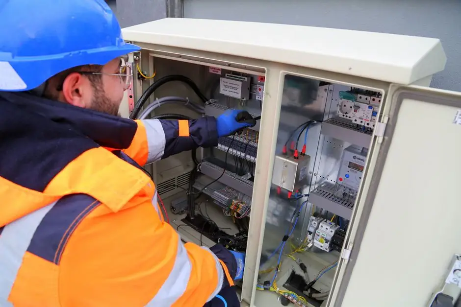
A distribution cabinet should be installed with adequate working clearance, structurally secure fixings, verified conductor polarity, and protective earthing before any circuit is energized [S2][S3].
This guide covers wall-mounted electrical distribution boxes, surface-mounted or recessed cabinet assemblies, and DC power distribution cabinets, with the controlling requirement being the manufacturer’s model-specific instruction rather than a generic installation sequence [S1][S5].
Confirm cabinet type, model, and mounting method
An electrical distribution box contains protective devices such as circuit breakers, fuses, and isolators that distribute power across multiple circuits; residential, commercial, and industrial installations differ in device arrangement and environmental demands [S2].
For the Main Line Cabinet Series, both surface mounting and recess mounting are permitted, but each model has dimensions and a specific mounting instruction; its manual also states that an improper installation voids the warranty [S5]. The broader cabinet installation literature likewise requires the installer to identify the exact construction and use the appropriate fasteners rather than substituting generic fixings [S4].
Consult the cabinet's model-specific dimensions and mounting instructions to determine the appropriate configuration. Fiber optic products have product-specific installation manuals [S1].
Position the cabinet for safe access and cable routing
The cabinet location must permit access by electricians and maintenance personnel while keeping the enclosure away from water, flammable or explosive substances, and corrosive materials [S2].
Confirm the intended circuit routes before mounting. A DC power distribution cabinet receives BUS+ and BUS- cables at the corresponding positive and negative terminals of the DC transfer copper bar, making polarity verification a physical installation and commissioning control rather than a paperwork-only check [S3].
Allow the specified service, door-swing, cable-bend, and ventilation space around the enclosure. The supplied research does not provide a universal clearance dimension for every cabinet, so use the approved drawings and manufacturer’s installation manual instead of adopting a generic 0.6 m or 1.0 m working clearance. Replace the cabinet rather than proceeding if the selected model cannot be mounted in the available envelope.
Mount the enclosure without distortion

Align the distribution box with its installation surface and the expansion-bolt or other specified fixing positions, then tighten the fasteners to produce a secure, plumb attachment without twisting the enclosure [S2]. The structure must support the cabinet and its installed equipment; the American Woodmark guide applies only to wood-stud construction and specifically prohibits nails and drywall screws for cabinet attachment [S4].
For surface and recessed assemblies, use the exact parts and fasteners listed for the selected configuration. The Main Line series documentation covers surface- and recess-mounted configurations [S5].
After mounting, operate every door, gland plate, lock, and removable panel. Alignment defects, binding hinges, distorted openings, or damaged finishes indicate improper mounting. Correct the support or fixings before cable termination; do not force the cabinet into service to hide the mismatch.
Prepare entries, conductors, and protective devices
Installation instructions are provided for a horizontal cable gland piece and a standard closing mechanism [S6]. Use only entries intended for the cabinet construction, environmental rating, cable type, and conductor size. Deburr conductor insulation, avoid damaging conductor strands, and maintain the manufacturer’s phase and neutral segregation.
For power cabinets, connect incoming feeders, outgoing branch circuits, busbars, and protective devices according to the approved single-line diagram and terminal schedule. In a DC power distribution cabinet, BUS+ must go to the positive transfer-bar terminal and BUS- to the negative terminal; an incorrect polarity connection must be corrected before closing the cabinet [S3].
Where overcurrent protection is fitted, verify that the breaker, fuse, or isolator rating matches the conductor and load design rather than relying on the cabinet’s nominal capacity [S2]. Replace damaged devices, missing covers, incorrect fuse links, or terminals that cannot be tightened to the specified torque. A terminal that cannot achieve a stable, properly torqued connection is an escalation point, not a field repair.
Ground the cabinet and verify protective arrangements

An electrical-option cabinet must be connected to a grounded metal, permanent wiring system, or have an equipment-grounding conductor run with the circuit conductors and connected to the cabinet’s equipment-grounding terminal or lead [S5]. Where the cabinet supplies bathroom or similarly designated loads, the Robern instruction requires a Class A 20 A GFCI-protected circuit in locations required by the National Electrical Code [S5].
Use the RCD, RCBO, breaker, fuse, and isolator arrangements required by the electrical design. The reviewed installation guidance identifies RCDs and RCBOs as possible additions to conventional breaker, fuse, and isolator layouts, but it does not specify a universal residual-current threshold for every installation [S2].
Check continuity of the protective conductor and verify that exposed metal is bonded as required by the approved design. Confirm the protective device remains isolated when the cabinet is open where that isolation function is required. Do not energize a cabinet with an unresolved earth fault, damaged bonding point, missing gland, or open panel joint.
Test before energization and define acceptance criteria
Before energization, inspect fastener security, door operation, gland tightness, conductor support, phase and polarity markings, protective-earthing connections, and the absence of loose tools or debris [S2][S3]. Confirm that the installed model matches the approved schedule and that every required conductor is present, correctly terminated, and suitably torqued.
Commission electrically in controlled stages: verify incoming isolation, insulation and continuity under the approved test procedure, then energize incoming supply and outgoing circuits individually with protective devices in the designated closed position. Record the measured results, protective-device settings, and corrective work in the commissioning file. Any failed insulation or continuity result requires isolation and investigation before retrying.
Set a maintenance interval from the equipment condition, site environment, duty cycle, and applicable safety regime rather than claiming a universal interval unsupported by the research. After installation, inspect terminals, doors, glands, and internal components for heat, corrosion, moisture, or loose connections, and escalate any overheating or repeated protective-device operation to an electrical engineer [S2].
Compare the principal installation routes
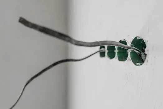
Surface mounting is generally the practical choice where masonry or structural walls provide direct fixing points and the enclosure depth is available; the Main Line documentation provides a dedicated surface-mount kit and identifies 30 and 40 height options [S5]. Recess mounting suits constrained walls, but it requires model-specific cutout dimensions, wall preparation, and final alignment, so it carries greater dimensional risk than surface mounting.
Outdoor electrical distribution boxes require a suitable enclosure and verified weather protection, while indoor boxes still require clearance from moisture and corrosive substances [S2]. DC distribution cabinets add a strict polarity and busbar-termination requirement, with BUS+ connected to positive and BUS- to negative [S3].
For a detailed comparison of enclosure options, the power distribution box entry provides useful terminology context. For installations centered on breaker-protected final circuits, the circuit breaker installation guide extends the commissioning sequence, while the MCC cabinet reference covers the broader distinction between a distribution enclosure and a motor-control assembly.