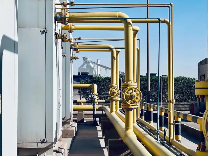
Desalination balancing valves should be selected from required nominal flow, pressure drop, and pipe arrangement rather than nominal pipe size alone.
The duty spans raw seawater, pretreatment, high-pressure reverse osmosis, concentrate, and post-treatment systems, with manual, pneumatic, electric, or hydraulic actuation considered against operating frequency and control requirements [S1][S2].
Define the balancing duty by system stage
Reverse osmosis requires more than an isolation valve: the balancing function must establish a reproducible flow split across membrane trains, vessels, or skid branches, while tolerating high pressure and changing seawater conditions [S1][S2].
Raw seawater and pretreatment lines may contain suspended solids, microorganisms, biofouling, and treatment chemicals, so seat material and surface finish must be evaluated against erosion, chemical attack, and fouling risk [S5]. High-pressure RO and concentrate circuits require a pressure rating suitable for the relevant train pressure, while post-treatment branches may instead be dictated by mineral dosing, CO₂ addition, and pH-adjustment flow [S2][S5].
The operating envelope should record design flow, minimum and maximum expected flow, differential pressure, fluid temperature, salinity or concentration, chloride exposure, and cycle frequency. A balancing valve used in a 100-coil example was preset to position 1.0 on coils designed below 0.75 inches water column to reduce future debris blockage, while 35 valves from 3/4 inch to 2-1/2 inches remained fully open for initial flow measurements [S3].
Size from flow and pressure drop, not pipe diameter
The governing sizing rule is direct: “Balancing valves should be sized in accordance with the GPM flows and not in relation to pipeline size” [S3]. For desalination, translate that rule into the required branch flow in cubic metres per hour or litres per minute and then verify the selected valve can pass that duty at the installed differential pressure.
In the cited installation, TA balancing valves were preset to 1.0 on the dial for terminal-unit reheat coils with design pressure drops below 0.75 inches water column, while valves ranging from 3/4 inch to 2-1/2 inches were set fully open [S3]. The cited installation involved 100 coils, including 65 with 3/4-inch balancing valves and 35 with valves ranging from 3/4 inch to 2-1/2 inches [S3].
Do not use the broad pipe-size guidance for every valve function indiscriminately. For seawater isolation valves, small diameters below DN50 are commonly assigned to ball valves, while DN65 to DN300 lines may use either ball or butterfly arrangements depending on pressure, duty, and control needs [S6]. That guidance concerns valve type selection, not hydraulic sizing of a balancing element.
Compare balancing valve configurations
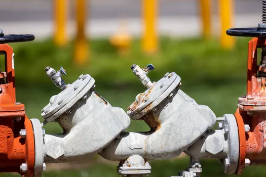
A conventional throttling balancing valve is appropriate when accurate, repeatable flow adjustment is required during commissioning and stable operation; its selection must be based on nominal flow, available pressure drop, pipe size, and the required adjustment range [S3].
For rapid hydraulic changes, a globe-type regulating valve can provide stronger throttling control than a simple isolation valve, but it requires a verified pressure-drop and actuator-sizing calculation. A segmented or high-performance ball valve with characterized flow control can suit large-diameter or high-pressure duties where tight shutoff and controlled modulation are both required [S5].
Actuation is not a secondary detail: manual operation suits infrequent commissioning or isolation, while pneumatic, electric, or hydraulic actuation supports automated sequencing and remote balancing. Available options include all four methods, and selection should consider operating frequency, response time, closure precision, and maintenance access [S1][S2].
Match seawater materials, seats, and pressure rating
The body, trim, stem, seat, and fasteners must be reviewed as a material set, because a corrosion-resistant body does not compensate for an unsuitable seat or stem. Seawater selection commonly considers stainless steel and titanium, while pretreatment valves may also require peroxide-cured EPDM, nylon-coated discs, or duplex-disc configurations [S2][S5].
For RO service, specify the design pressure for the actual train arrangement, including the allowable operating and test pressures defined by the project. Valve suppliers describe seawater valves as requiring high-pressure tolerance, but the purchasing specification must still state the actual pressure class and test requirements rather than relying on a generic seawater label [S2].
Temperature, salinity, concentration, dosing chemistry, and biofouling determine material and seat compatibility [S1][S2]. The same seawater chemistry can change across the plant: pretreatment sees aggressive treatment chemicals, RO sees high-pressure feed, and post-treatment handles corrosive brine streams and acidic permeate remineralization conditions [S5].
Build commissioning and maintenance access into the selection
Balancing performance must be measurable, repeatable, and serviceable without removing critical pipework. The cited installation used TA balancing-valve differential-pressure ports for balancing, preset the valves for terminal-unit reheat coils below 0.75 inches water column to 1.0 on the dial to reduce the risk of debris blockage, and set the remaining valves fully open [S3].
Strainers, pressure gauges, test ports, drainability, stem orientation, actuator clearance, and access for disassembly and cleaning affect the installed result. Seawater valve suppliers specifically identify ease of disassembly and cleaning as important in contaminant-heavy environments, while installation compatibility requires checking nominal sizes, connections, and available space [S2].
Debris protection is not optional. In the cited balancing application, valves serving coils with design pressure drop below 0.75 inches water column were initially held at setting 1.0 rather than throttled further, specifically to limit the risk of debris accumulation and blockage [S3].
Know when balancing is the wrong valve choice
A balancing valve is the wrong selection where the required function is only on/off isolation, rapid emergency closure, or check-valve flow prevention. Those duties belong to a full-bore isolation valve, safety isolation device, or axial-flow check valve, selected for shutoff, pressure class, corrosion resistance, and actuation fail action rather than branch-flow adjustment. [S4]
Do not select a balancing valve by line diameter alone, by broad minimum-to-maximum flow ranges, or by matching a pipe flange size. These shortcuts caused 13 undersized valves in the documented project and produced schedule and cost consequences because only three could be replaced immediately [S3].
Do not transfer an HVAC-style balanced-branch assumption unchanged into an RO skid. Membrane-train hydraulics, high feed pressure, concentrate flow, pretreatment fouling, and post-treatment chemistry create different material and control requirements, even when the balancing principle remains the same [S1][S2].
Specify, verify, and retain the selection evidence
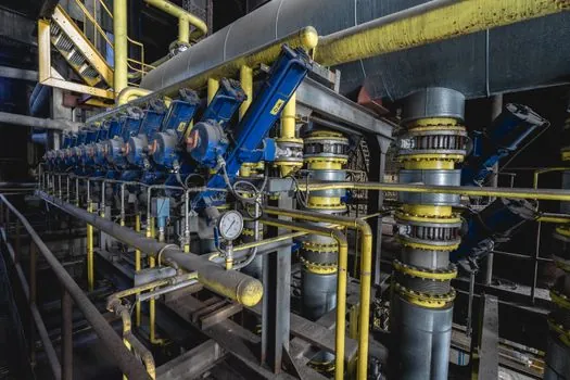
The procurement package should identify each system stage, fluid service, nominal flow, minimum and maximum flow, design and test pressure, differential-pressure range, temperature, material grade, seat type, end connection, actuator method, fail position, allowable pressure drop, and required access [S1][S2].
Hydraulic verification must use the actual valve flow coefficient and the installed pressure drop rather than pipe diameter. For measurement and documentation, the package should also identify the instrument range, test locations, balancing procedure, acceptance tolerance, and maintenance access. VERSA lists 10-day lead times for more than 30,000 parts and a 10-year product warranty as commercial data, while its desalination portfolio covers material options including stainless steel and aluminum; these figures should be treated as supplier-specific rather than universal plant specifications [S4].
For alternative service-specific guidance, see Balancing Valve Selection for Chemical Processing, then compare it with seawater corrosion, high-pressure RO, and concentrate-service requirements before approving a valve schedule.
The next verification node is the approved hydraulic calculation and valve data sheet; the two trackable signals are measured branch flow versus valve position and valve operating-temperature or pressure margin against the specified envelope.