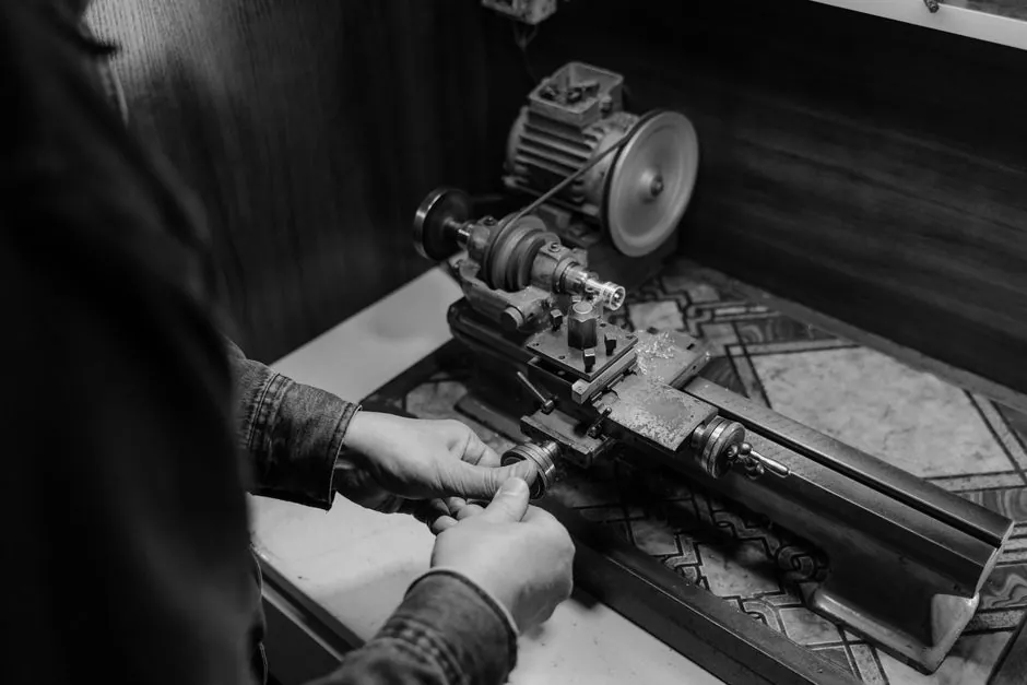
On a horizontal dynamic balancing machine, the drive train sets the practical ceiling for rotor weight, run-up torque, and achievable residual unbalance more than the measuring system does [S3].
Three arrangements dominate the spec sheets in 2026: belt drive, end drive, and self drive (also called universal-joint or cardan drive), with combined belt-plus-end machines offered as a fourth option [S2]. Picking among them is a function of rotor weight, available torque, journal access, and whether the part is shaft-mounted or has no shaft at all.
How the three drive types actually engage the rotor
A belt drive balancing machine uses a thin belt wrapped over the rotor periphery or a pulley attached to the shaft; its main advantage is that the belt's mass and stiffness contribute only a small error to the unbalance measurement, because the belt itself is light and the contact point is on the rotor surface [S2][S3]. Torque transmission is, however, limited by belt friction and wrap angle, which is why belt drive is generally paired with rotors under a few hundred kilograms and at moderate speeds [S3].
An end drive machine engages the rotor through a universal joint or flexible coupling on the shaft end, transmitting full motor torque directly into the part [S1][S3]. A positive end drive is the only practical option for rotors with high inertia or for high-speed balancing where the rotor must not lift off its pedestals under centrifugal load [S1].
A self drive arrangement, sometimes marketed as universal-joint or cardan drive, is essentially an end drive applied to rotors whose shaft cannot accept a coupling, for example open impellers, flywheels, or components with no protruding journal [S1]. Some suppliers further distinguish a combination drive that carries both a belt headstock and an end-drive spindle on the same bed, letting the operator swap the drive type without re-fixturing the rotor [S2].
Weight, diameter, and speed envelope by drive type
Rokade's end drive range illustrates the upper envelope for that architecture: ten standard models spanning 50 kg to 30000 kg weight capacity, with maximum rotor diameters from 500 mm on the H 50 up to 4000 mm on the H 30K, and journal diameter coverage from 8-50 mm on the smallest frame to 70-350 mm on the H 16K and H 30K [S1]. Bed lengths on those frames run from 800 mm short-bed to 7500 mm long-bed configurations [S1].
End drive speed is infinitely variable through a VFD, with the actual speed ceiling set by the machine model and by safety enclosure rating; the electronics handle the multi-speed calibration transparently so the unbalance number does not drift with rpm [S1]. This is critical because, on a self-aligning bearing pedestal, the rotor's critical modes shift as run-up speed passes them, and the controller must remain in calibration across that band.
Belt drive machines, in contrast, are typically specified for rotors from a few hundred grams up to a few hundred kilograms, with the belt limiting achievable torque and therefore the practical run-up rate [S2][S3]. Within that envelope, however, belt drive routinely achieves the lowest residual unbalance on the part, because the drive does not preload the shaft axially and introduces almost no parasitic moment into the measurement plane [S3].
Decision matrix: belt vs end vs self drive against four criteria
The decision reduces to four engineering criteria: maximum rotor weight, available drive torque, residual unbalance target, and shaft accessibility. End drive wins on the first two, belt drive wins on the third, and self drive wins on the fourth when no shaft is available. [S3]
For a part weighing more than 1000 kg, for example a paper machine roll, a motor armature, a turbine rotor, or a crusher shaft, end drive is essentially the only option on a horizontal machine [S1]. Within the 50-1000 kg band, the choice between belt and end depends on whether the part has a usable journal and whether the operator needs to run the rotor at a precise test speed that the belt cannot hold under load. For a 300 kg armature with stub shafts, belt drive on the commutator is often selected because it gives the cleanest unbalance reading; for the same 300 kg armature run at high speed, an end drive with universal coupling is selected to prevent lift-off [S1][S2].
Self drive fits the awkward middle: parts with a centre bore and outer diameter larger than the axial length, including flywheels, brake discs, clutches, grinding wheels, and pump impellers, which are typically balanced on vertical-axis machines but can also be run horizontally with a self-drive mandrel engaging the bore [S1][S2]. When the part is purely disc-shaped, a belt conveyor-style wrap drive is also a documented option, with the belt providing both rotation and axial constraint.
Application list and rotor examples from manufacturer data
End drive machines are the default for blower impellers, motor rotors, paper machine rolls, centrifuges, crushers, turbine rotors, pulleys, hubs, crankshafts, armatures, fans, and compressors, with the most common Rokade reference parts being large industrial rotors where high inertia dominates run-up behaviour [S1]. Belt drive machines are the default for armatures, textile and machine spindles, shafts, turbines, printing and paper rollers, and submersible pump rotors, where the rotor mass is moderate and the shaft can be reached by a thin belt [S2].
Self drive machines dominate vertical balancing cells for flywheels, pulleys, pump impellers, grinding wheels, car wheels, brake discs, and clutches, where the rotor is mounted on a vertical mandrel and driven through the bore [S2]. Where the part has neither bore nor shaft, an air-jet drive is the only remaining option and is occasionally integrated as a fourth mode on universal horizontal balancing machines, primarily for very small rotors that cannot tolerate any mechanical drive contact [S3].
Standards, calibration, and common failure modes
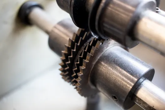
For rotors that run in rolling element bearings, the balancing machine reference standard is to support the rotor on its own journals, or in its own bearings held in V-roller carriages; rolling element bearings below ABEC 3 grade limit achievable balance quality and should be replaced before final trim balancing [S3]. Where the rotor is supported on more than two journals, all journal surfaces must be concentric with the axis defined by the two used on the machine, otherwise the residual reading carries a systematic error from shaft straightness rather than from real unbalance [S3].
Belt drive's main calibration risk is belt-mass contribution to the unbalance vector; it is small but not zero, and periodic re-calibration with a witness rotor is standard practice [S3]. End drive's main risk is that a worn universal joint or flexible coupling injects a periodic error at one-per-revolution that masks the true unbalance, especially on a self-priming pump impeller with an overhung shaft. Self drive's main risk is mandrel concentricity: if the mandrel runout exceeds the journal tolerance of the rotor's bore, the measured unbalance reads high in the same angular position every revolution, leading to over-correction.
A self-cleaning filter style self-diagnostic in the controller, where the software flags a non-random unbalance signature, is the practical mitigation. On combination-drive machines the operator should also re-calibrate after switching between belt and end modes, because the two drive paths have different parasitic stiffness and produce different baseline vectors on the same rotor [S2].
Selection checklist and 2026 supplier signal
Use end drive as the default for any rotor above 1000 kg, any rotor with high inertia, any rotor to be balanced at a precise high test speed, and any rotor where lift-off on the pedestals is a concern; Rokade's H 1K through H 30K covers 1000-30000 kg in this class [S1]. Use belt drive for light and medium rotors under a few hundred kilograms where the shaft or a dedicated pulley can be reached by a thin belt, and where the lowest residual unbalance is the priority [S2][S3]. Use self drive (cardan or universal-joint) when the rotor has no usable shaft journal, for example large impellers, or when a combination belt-and-end machine is already on the floor and only the drive mode needs to change [S1][S2].
The 2026 supplier signal worth tracking is the spread of combination-drive machines from Indian OEMs such as Precibalance and Rokade, which now ship end and belt drive on a common bed with VFD headstock and permanently calibrated electronics as standard, a configuration that five years ago was a custom build [S1][S2]. The next decision node for a buyer is whether the rotor's required test speed exceeds what a belt can hold under that rotor's specific torque load; if it does, specify end drive regardless of weight. For related sizing logic on adjacent rotating equipment, the spec approach used for a balancing valve selection, where you pick by flow range and tolerance band rather than by nominal size, applies cleanly to drive selection here.
For related coverage, see Base GC Instrument Price vs Added Detector Cost: 2026 Buyer Map.