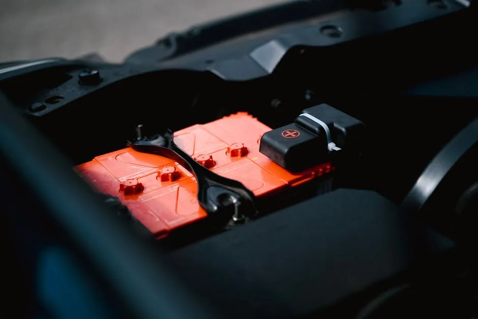
A grid-scale battery energy storage system is, in practice, a stack of five subsystems that must agree in real time: cells, Battery Management System (BMS), Power Conversion System (PCS), Energy Management System (EMS), and the plant controller (PPC) that sits above all of them [S3]. Failure modes are rarely dramatic cell death; they show up as accelerated capacity fade in a handful of cells or a rack that quietly underperforms its neighbors because the BMS is not enforcing the state-of-charge window correctly [S3].
Across the past six months, vendor and integrator literature has converged on a common architectural picture: certified power plant controllers, vendor-agnostic battery interfaces, and a fast industrial bus for inverter-to-controller traffic. Power Electronics, for example, has built 3000+ solar and storage projects totaling 120 GW and now switches a 330 MW load step in 110 ms using Beckhoff CX-series embedded PCs with TwinCAT 3 and Modbus TCP links to every BCI [S2]. Gantner pairs a certified PPC with an integrated BESS controller in a single scalable package and exposes peak shaving, ramp rate, frequency, voltage, power factor, and black-start as core control functions [S4]. Emerson markets its DeltaV and Ovation DCS families, plus the Rosemount and Micro Motion instrument brands, as the management and measurement layer for BESS plants [S1].
Subsystem boundaries: what each control layer actually owns
The BMS is the cell-protective layer. It monitors cell voltage, temperature, and current at the module level, balances weaker cells against stronger neighbors, and trips disconnects on overcurrent, overtemperature, or communication loss [S3]. In a typical LFP build, a prismatic cell sits near 3.2 V nominal; 16 cells in series give about 51.2 V per module, and several modules in series put a rack at 600 to 1,000+ VDC [S3]. That voltage hierarchy is the BMS's domain, not the PCS's.
The PCS is the bidirectional inverter that turns rack DC into grid-compliant AC and vice versa, and it sets the hard ceiling on charge and discharge power in kW regardless of how many kWh sit behind it [S3]. Undersize the PCS relative to battery capacity, and a 2 MWh system behind a 500 kW inverter still tops out at 500 kW: acceptable for long-duration duty, a real problem when the application needs fast power response [S3]. Above the PCS, the EMS decides when to charge, discharge, hold, or export, while the PPC enforces grid code and dispatches the setpoints that the EMS has negotiated.
Field bus and controller choice: Modbus TCP, embedded PCs, and short cycle times
Power Electronics' standard architecture uses a CX5120 or CX5240 embedded PC with Intel Atom as each Battery Controller Interface, running TwinCAT 3 PLC and talking to inverters, batteries, and other block components over Modbus TCP [S2]. The control loop is short by design: Power Electronics has driven the 150 MW to 180 MW load step transition from 130 ms down to 110 ms by tightening the BCI cycle time and using PC-based control rather than a classic PLC scan [S2]. For hybrid blocks, where one inverter manages both PV and batteries simultaneously, the BCI must hold an autonomous energy balance between the two sources without operator intervention [S2].
Gantner's BESS package takes a different tack: a single certified PPC and integrated BESS controller in one chassis, Modbus-compatible with third-party devices, designed for vendor-independent multi-OEM plants [S4]. The same control surface supports peak shaving, energy shifting, ramp-rate management, frequency and voltage control, power factor and reactive power control, self-consumption optimization, and black start [S4]. For a process engineer building a new BESS, the practical decision is whether to standardize on one vendor's PPC stack (Emerson DeltaV/Ovation) or use a vendor-agnostic BCI/PPC pair (Beckhoff + TwinCAT, or Gantner.BESS) wired to third-party inverters.
Cell-level diagnostics: EIS and the move from reactive to predictive BMS

Electrochemical impedance spectroscopy has moved from a lab instrument to a cell-level BMS function in 2026. Integrated EIS engines, such as the Texas Instruments BQ79826Z-Q1, excite cells with AC current across a frequency range and extract impedance data that fingerprints the cell's chemistry, age, and operating condition in real time [S5]. The Nyquist plot is still the standard analysis tool: plotting impedance across frequencies gives separate information on cell temperature, anode and cathode state, lithium diffusion, and solid electrolyte interphase (SEI) growth, none of which a passive voltage and temperature monitor can resolve [S5].
For high-cell-count systems, the pitch is safety and reliability: thermal runaway in a thousand-cell rack is far more destructive than in a small pack, and EIS gives the BMS enough lead time to flag a cell before it goes hard-fault [S5]. The engineering trade is sample rate and bus load: an EIS sweep across thousands of cells competes with normal BMS telemetry, so the cell monitor's measurement budget has to be sized against the comms stack, not just the analog front end. For more on how diagnostic electronics change battery selection, see this TOPCon cell cost breakdown 2026 piece on a related monitoring-density problem in PV manufacturing.
Selection criteria: who a BESS control architecture is for, and who it is not for
Vendor-integrated stacks (Emerson, Gantner, Power Electronics) suit plants where one party takes EPC responsibility and the operator wants a single support contract. A certified PPC with documented grid-code compliance, integrated BESS controller, and built-in logging is the right shape for utility-scale and C&I sites that must demonstrate frequency response, voltage support, or black-start capability to a grid operator [S4].
Vendor-agnostic stacks built on Beckhoff CX PCs, TwinCAT 3, and Modbus TCP suit EPCs and owners who want freedom to swap inverters, batteries, and even PPC software across multi-vendor fleets, or who already run a Beckhoff or PC-based control fleet on the process side [S2]. The trade is integration labor: the BCI cycle time, the PPC-to-BCI protocol, and the grid-code mapping are all owned by the integrator. For a pharmaceutical plant evaluating 1500 kWh of BES behind a 1 MW PV system, the S0360544226014416 study frames the operating envelope: net-metering rules, demand-charge structure, and self-consumption targets drive the EMS dispatch logic more than the cell chemistry does [S6].
Criteria-based comparison: control options against four engineering axes
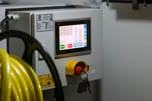
On control cycle time, vendor-agnostic PC-based BCIs hit 110 ms for a 330 MW step (Power Electronics on Beckhoff) [S2], while certified PPC platforms like Gantner.BESS trade raw speed for documented grid-code compliance and Modbus interoperability [S4]. On interoperability, Gantner and Beckhoff-based stacks expose Modbus TCP to third-party inverters and batteries; vendor-integrated DCS stacks are smoother inside their own brand family but require gateways for everything else [S1][S2][S4]. On diagnostics depth, an EIS-enabled BMS like the BQ79826Z-Q1 adds cell-level impedance, Nyquist analysis, and predictive fault flagging beyond voltage and temperature BMS [S5]. On EPC scope, an Emerson or Gantner single-vendor package carries one support contract; a Beckhoff + third-party inverter build splits it across two or more. The choice is usually a function of who owns grid-code liability and how heterogeneous the inverter fleet will be.
Process control context: where BESS control meets the wider plant
BESS control is, in essence, a fast power layer bolted onto a slower process-control plant. The same logic that governs a chiller loop or a fired heater also governs the round-trip efficiency of a battery rack, and the same measurement stack (pressure, temperature, flow, level, gas analysis) sits around the thermal management skid. For the broader instrumentation and control picture, see the process control reference and the energy management reference. When BESS is co-sited with generation and storage infrastructure, the rack and handling choices also matter, as covered in the storage rack and storage handling encyclopedia pages. For the metering side of the AC interface, the energy meter reference is the right starting point. On the sizing and instrumentation side, this level switch sizing piece shows the same duty-driven spec logic that should govern BMS and PCS selection. [S1]
Track, over the next quarter, how many multi-MW BESS sites ship with a documented EIS-enabled BMS versus a classic voltage-and-temperature BMS, and whether certified PPC platforms (Gantner, Emerson) absorb third-party inverter brands faster than vendor-agnostic PC-based BCIs do.