
A battery management system (BMS) is the electronic assembly that sits between a lithium-ion or LiFePO4 pack and its loads/chargers, performing sensing, state estimation, balancing, and contactor control; commercially built units in 2026 typically expose 0-60 V / 0-120 V / 0-240 V monitoring ranges at 1.0-3.6 mV resolution with 0.1% accuracy across per-cell channels [S4].
Process scope on a modern BMS line covers incoming IC/PCB QA, SMT assembly of the cell-monitoring front-end and microcontroller, conformal coating, firmware flash, end-of-line cell-voltage calibration, HiPot isolation test, and pack-level burn-in; MathWorks' Simscape Battery block library, current as of the 2026-06-14 documentation update, treats cell balancing, current management, state-of-charge (SOC) / state-of-health (SOH) estimators, protection logic, and cyclers as separate deployable Simulink subsystems [S1].
BMS Architecture and Functional Blocks Specified on 2026 Production Lines
Every production BMS converges on the same five functional blocks regardless of vendor: cell voltage/temperature sensing, current sensing, a state estimator (SOC/SOH), a protection matrix, and a balancing network; the Texas Instruments TIDUCN1 reference design for multicell 36-48 V packs lists over- and under-voltage, over- and under-temperature, over-current, and short-circuit discharge as the canonical protection set, with a 100 mA passive-balancing current budget per cell and 1-30 Ah gauging [S5].
The same TI reference confirms 12 to 15 cells in series, 36-48 V nominal input, and a state-of-charge/status communication port — the same building blocks appear, scaled, in automotive packs; Infineon's automotive BMS portfolio segments its offering by voltage rail (12 V, 24 V, 48 V, high-voltage) and function (cell monitoring & balancing, battery control unit/BCU, isolated communication, pack monitoring, battery passport & event logging, protection & disconnection) [S10]. The split between cell-monitoring front-end (analog, high-voltage-tolerant) and the BCU (digital, low-voltage, communication-rich) is the dominant partitioning rule on a 2026 automotive BMS line.
Sensing, ADC Resolution, and Voltage-Monitoring Spec Bands
An S-Series BMS data sheet publishes 1.2 mV resolution on a 0-5 V low channel with 5 mV error, 1.2 mV resolution on a 0-5 V high channel with 5 mV error, and pack monitoring ranges of 0-60 V (1.0 mV), 0-120 V (1.8 mV) and 0-240 V (3.6 mV) at 0.1% accuracy [S4].
That resolution envelope matches what TI's bq27220 and Maxim's ModelGauge single-cell fuel-gauge ICs implement as the cell-side front end — both measure voltage and temperature and estimate SOC, with the TI part adding current sensing for coulomb-counting [S6]. Temperature is read with on-cell NTC/PTC channels; the REC 4-15S BMS datasheet specifies a cell over-temperature switch-off at 60 °C, a BMS-level over-temperature switch-off at 50 °C with 5 °C hysteresis, and a charging disable below -15 °C [S9]. Current sensing on higher-end modules is a Hall-effect or shunt-plus-isolated-amplifier front end feeding the estimator, with the protection matrix acting on the same signal within microseconds.
State Estimation: SOC, SOH, and the Coulomb-Count vs Kalman-Filter Split
SOC estimation is split between two industry-standard techniques that every 2026 BMS must pick between: coulomb counting (current integration, simple, drift-prone) and the Kalman filter (model-based, tolerant of noisy and biased sensors); MathWorks' Simscape Battery 'Estimate Battery SOC Using Kalman Filter' example, marked "Since R2024b", models both and demonstrates Kalman recovery from inaccurate initial conditions [S1].
SOH (state of health) is the slower-varying companion metric — capacity fade and internal-resistance growth — and is implemented as a separate estimator block in the same Simscape library [S1]. The UCCS ECE5720 lecture notes summarise the same trade-off in functional terms: sensing and high-voltage control, protection against over-charge / over-discharge / over-current / short circuit / extreme temperature, and the interface layer that delivers range estimation, communications, and data recording [S8]. On a real line this means two firmware binaries (SOC and SOH estimators) and two calibration tables per cell chemistry.
Balancing Topologies: Passive Resistor vs Active Shunt, with Process Implications
Cell balancing is mandatory on any series string of three or more cells; ScienceDirect's overview states that an overcharged module can be partially discharged through a resistor (passive balancing) or the charger can be redirected to lower-voltage modules while bypassing the highest one (active balancing) [S7]. The choice is not engineering-debate territory in 2026 — passive is dominant on cost-driven 12-48 V packs because it adds one resistor and one switch per cell, while active (capacitive or inductive shuttles) wins on efficiency for high-cell-count EV packs.
Manufacturing consequence: a passive-balancing line needs an SMT step for discharge resistors and a single thermal test on the resistor array; an active-balancing line adds a second inductor/capacitor array, a separate balancing-IC placement, and 100% test on the DC-DC transfer efficiency. MathWorks' Simscape 'Cell Balancing' block library handles both topologies as Simulink subsystems that can be sized and simulated before PCB commit [S1].
Pack Integration: Contactor Control, Pre-Charge, and Ground-Fault Detection
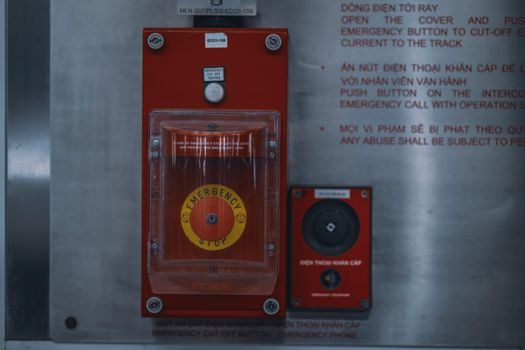
Once the cell-monitoring and balancing PCB is built, the pack-level BMS adds contactor drivers, pre-charge circuitry, and ground-fault detection on the high-voltage bus; the UCCS notes list contactor control, pre-charge, and ground-fault detection as the high-voltage-control responsibilities of the sensing block [S8]. Victron's Lynx Smart BMS integrates a safety DC contactor rated at 500 A or 1000 A (model-dependent) that disconnects the system from the battery bank on a cell voltage or temperature alarm and doubles as a main on/off switch [S3].
Smaller units rely on solid-state switches and relay outputs — the REC BMS specifies a max DC relay current of 0.7 A at 60 V DC, 2 A at 230 V AC, and a 62.5 V / 15 mA optocoupler output channel for external signalling [S9]. End-of-line test on this section is a HiPot / isolation-resistance check across the high-voltage/low-voltage barrier (typically 500 V DC or 2.5 kV AC for one second) plus a contactor-wear cycle test. For a deeper view of how the upstream cell is built before the BMS is married to it, see the battery cell manufacturing process spec stack.
Communications, Safety Targets, and Functional-Safety Stack
Automotive-grade BMS hardware is selected and laid out against ISO 26262 ASIL-C (cell monitoring) and ASIL-D (pack-level contactor control); Infineon segments its offering into cell monitoring & balancing, isolated communication (typically CAN-FD or SPI-isolated daisy chain), the BCU, and a separate high-voltage disconnect path [S10]. Stationary packs in 12-48 V architectures are typically built to a lower functional-safety target but still expose state-of-charge, status, and alarms over CAN, RS-485, or Bluetooth — all Victron 'Smart' BMS models include Bluetooth and the VictronConnect app for parameterisation [S3].
Event logging and the EU 'battery passport' are emerging as a separate sub-system on 2026 lines: Infineon lists 'battery passport & event logging' as a distinct application block, and the IEEE Std 1547-2018 grid-interactive behaviour is the reference for peak-shaving BESS controllers in the same Simscape example set [S1][S10]. On a manufacturing line this adds a secure-memory IC, a real-time clock, and a signed-log block to the bill of materials. For pack-makers who source balancing ICs and protection MOSFETs, the upstream lithium OEM vs ODM manufacturing landscape tracks which vendors are still running qualifying production for those parts in 2026.
Comparison: Passive vs Active Balancing vs Contactors, on Four Production Criteria
On a 2026 line the choice of balancing and disconnection topology drives four measurable decisions: bill-of-materials cost per cell, balancing efficiency, end-of-line test time, and achievable ASIL level. Solid-state contactor output (REC-style 0.7 A at 60 V DC optocoupler) is the lowest-cost disconnect path and suits small packs; Victron Lynx-style safety DC contactors (500 A or 1000 A) carry the main pack disconnect on yacht, RV, and ESS builds and require an additional electromechanical-wear test on EOL [S3][S9].
The TI multicell 36-48 V design positions itself in the middle: 100 mA passive balancing per cell, protection matrix covering all four canonical fault classes, and a 1-30 Ah gauging range that matches e-mobility light-electric and small-ESS packs [S5]. For cell-chemistry choices that drive the SOC/SOH estimator calibration tables, electrolyte smart manufacturing spec bands and the sodium-ion cell manufacturing process map cover the upstream variables a BMS has to model in firmware.
Selection Criteria: Which BMS Class Fits Which Build
Victron's own design-recommendation table is the clearest published decision rubric: SmallBMS for 12/24/48 V systems with no inverter/charger; VE.Bus BMS V2 for 12/24/48 V systems with inverter/chargers plus a GX device; Lynx Smart BMS for 12/24/48 V systems where a safety contactor is needed (yacht, RV, ESS); Smart BMS 12/200 for 12 V systems with a dedicated alternator input [S3]. The unstated rule: a maximum of 20 lithium batteries can be connected to a single Victron BMS, and the 12 V-only models (smallBMS excluded) cannot be reused on higher-voltage stacks [S3].
For automotive and high-voltage traction packs, Infineon's split by voltage rail (12 V, 24 V, 48 V, high-voltage) and by function (cell monitoring & balancing, BCU, isolated communication, pack monitoring, battery passport, protection & disconnection) is the de-facto BOM scaffold; the higher the voltage rail, the more aggressive the isolation test and the stricter the functional-safety target [S10]. Process engineers who also handle the upstream anode material manufacturing line should map the BMS cell-voltage window to the anode's actual SOC-OCV curve, not the chemistry datasheet default.
Manufacturing Test Stack and Failure Modes
A 2026 BMS production test sequence runs in this order: in-circuit test on the bare PCB, cell-simulator calibration on the populated board (forces known voltages into each cell channel and checks ADC against the 1.0-3.6 mV / 0.1% spec), firmware flash with cell-chemistry-specific SOC/SOH tables, HiPot / isolation-resistance test, contactor-wear cycle, and a 4- to 24-hour pack-level burn-in with simulated charge/discharge cycles [S4][S8][S9]. The most common field failure modes that the test must catch are drifted cell-voltage references (captured by the cell-simulator step), welded contactor contacts (captured by the contactor-wear cycle and the 0.7 A / 60 V DC REC-style relay spec), and NTC sensor disconnects that bypass the 60 °C cell over-temperature cutoff [S9].
Trackable signal for the next six months: TI, Infineon, and the Simscape Battery block set continue to publish reference designs and Simulink subsystem libraries that lock in the cell-balancing, estimator, and protection partitions [S1][S5][S10]; a process engineer building a new line in 2026 should baseline the BOM and EOL test plan against those three sources and against the IEC 61508 / ISO 26262 functional-safety target the pack is sold into. None of the datasheets cited publish a revision date later than 2026-06, so any post-June 2026 update to the Simscape Battery BMS block library, the TIDUCN1 reference, or the Victron overview datasheet is a verifiable next node to watch.
For component-level specifications, see additive manufacturing material, multifunction process calibrator, and v process line.