
A busway can distribute high-capacity power in ratings from 250 A to 5000 A at voltages up to 690 V and 50–60 Hz, using copper or aluminum conductors, insulation and a metal enclosure [S2].
It is a centralized alternative to conventional cable distribution for factories, high-rise buildings, mining, infrastructure and data centers, with suitability determined more by load profile, expansion plans, installation conditions and installed cost than by conductor capacity alone [S1][S3].
Where busway outperforms conventional cabling
A busway contains a metal enclosure, conductive bars and insulation that separates the conductors from each other and the housing; this construction supports centralized power allocation and physical protection against mechanical damage [S1].
Its practical advantage is modular routing. Straight sections, horizontal and vertical bends, tee sections, starting units and plug-in units can form a distribution backbone without pulling individual cables along every route [S2]. Compared with traditional cables, modular assembly reduces separate cable routing and wiring work, while additional tap-off units can be installed as loads develop [S3].
Busway also offers space efficiency and thermal performance. A compact, organized conductor system can replace large bundles of cables, and the enclosure permits heat dissipation through the busway structure; double-connected copper bars increase joint contact area and reduce temperature rise at connections [S1][S2].
These features make busway a strong option where several large loads need a common distribution route. Industrial plants, high-rise buildings and data centers are typical applications, while workshop refurbishments and expanding enterprises can benefit from the ability to extend or reposition distribution assets [S1][S2].
Cost, installation and operating constraints
That expenditure covers equipment, route preparation, supports, joints, tap-off units and installation labor rather than conductor material alone.
Installation also requires more precision than pulling individual cables. Sections must be aligned correctly and connections secured, with copper or aluminum busbars, insulation, housing and accessories forming a coordinated assembly [S1]. Busway insulation prevents shorts between conductive parts, while double-connected copper bars increase joint contact area and reduce joint temperature rise.
Environmental exposure can erase the space and installation benefits. Damp, corrosive or mechanically harsh locations require additional protection for busway components, while floor penetrations require waterproof detailing and coordinated avoidance of water pipes and fire sprinklers [S1][S2].
Busway is not automatically the better answer for every feeder. It makes the most sense where high-current loads justify a dedicated distribution backbone, route changes are probable, or space and installation coordination favor modular bus sections. Distributed small loads, simple retrofits and installations where busway hardware cannot be supported or protected may favor conventional cables.
Busway types compared by construction and use
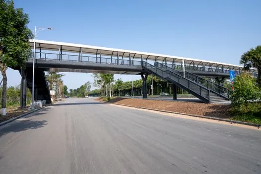
Busway systems can be divided into plug-in and feed-type arrangements: plug-in systems provide junction or tap-off boxes at intervals, while feed-type systems omit intermediate junction boxes and feed loads through the run [S2]. Plug-in busway therefore fits modular expansion and distributed takeoffs more directly, while feed-type busway suits a defined main route with fewer intermediate connections.
The comparison depends on four measurable criteria: initial expenditure, available space, installation labor and expansion flexibility. Busway generally wins on modular installation, tap-off expansion and routing density, while conventional cables generally win on first cost for simple installations; precision, protection and qualification requirements determine whether those busway benefits outweigh the added expenditure [S1][S2][S3].
Electrical design and fault-management requirements
Busway selection begins with the distribution duty: the published product scope covers AC three-phase four-wire and three-phase five-wire systems, 50–60 Hz, rated voltage up to 690 V and operating current from 250 A to 5000 A [S2]. Copper or aluminum conductors can suit the duty, but the busbar material and insulation system must be matched to the rated current, fault level, temperature rise and installation environment [S1].
Busway systems require measures to prevent water ingress where they pass through floors, while double-connected copper bars increase joint contact area and reduce joint temperature rise. A busway also requires coordination with the building distribution arrangement, including the role of associated distribution cabinets and the ratings of incoming and outgoing protective devices.
Where a high-current feeder is required, the busway should be compared with a cable distribution cabinet on busbar rating, short-circuit withstand, joint type, tap-off capacity, physical footprint and installed cost. These are engineering selection points, not interchangeable claims: the cabinet arrangement and busway rating must match the fault and load requirements of the installation.
Applications suited to busway distribution
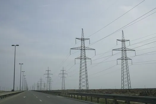
Busway is suited to industrial facilities with high-capacity production loads, commercial buildings with extensive electrical demand, and data centers feeding server and IT infrastructure [S1]. It is also used in substations, transportation systems, mining operations and other high-power infrastructure [S1][S2].
For data centers, modular busway can provide a structured route for power distribution and allow additional tap-off positions as capacity requirements change [S3]. Its compact geometry is useful where floor space and cable volume are constrained, but the installation still requires coordinated support, connection and protection planning.
For factories, mines and high-rise buildings, busway can serve as the main power line, with vertical runs through an electrical shaft in multi-route arrangements [S2]. Workshop and legacy-plant renovation is another valid use when concentrated loads need a new distribution backbone and cable routing would be difficult or space-consuming.
Specification checklist before approving busway
A busway specification should record at least the 250–5000 A current framework, voltage not exceeding 690 V, 50–60 Hz frequency, conductor material, insulation type, short-circuit withstand and environmental conditions [S2]. These values must be confirmed against the actual system because published busway families cover different ratings and constructions.
The route drawing should then fix straight, bend, tee, starting and tap-off sections, support locations, floor crossings, clearances and waterproofing details [S1][S2]. The commercial comparison should include equipment, labor, supports, protection and future tap-offs rather than a purchase-price comparison alone.
For a broader control-system comparison, the trade-offs differ from busway, as discussed in motor control center advantages and disadvantages. For busway itself, the defensible approval point is a load and route study that demonstrates adequate capacity, acceptable fault behavior, protected installation and a lifecycle benefit that offsets the higher installation burden.
The next trackable design signal is the planned load list: if it contains several high-current feeders, expected tap-offs and constrained routes, the busway case becomes measurable; if it consists mainly of small scattered loads, its higher first cost and installation demands require closer justification.