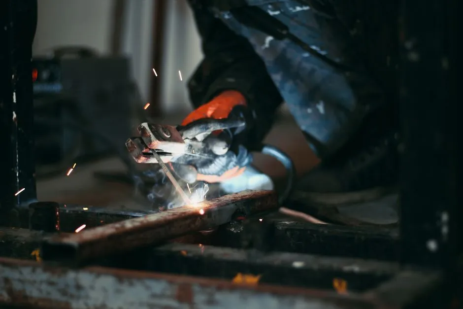
Capacitor discharge (CD) stud welding fires a stored-energy pulse of ≤3 ms to fuse a small-diameter stud (M3 to M10) onto thin sheet down to 0.5 mm, while drawn arc (DA) stud welding draws a sustained pilot-plus-main arc of 100-1500 ms to weld 2-25 mm studs onto plate ≥2 mm thick with a ceramic ferrule [S2][S3].
Both are one-sided, full-cross-section fastener processes governed by ISO 13918 for stud geometry, and they remain the two workhorses of industrial stud welding on 2026-09-23 shop floors, with short cycle (SC) sitting as a 20-100 ms hybrid between them [S3][S4].
Process Physics and Weld Time Envelope
CD stud welding stores energy in a capacitor bank charged to a preset voltage and dumps that energy as a high-current pulse; HBS contact-mode CD welds complete in ≤3 ms and gap-mode CD in approximately 1 ms, which is what lets the process fuse aluminium, brass, mild steel, and stainless onto 0.5 mm sheet without burn-through [S2].
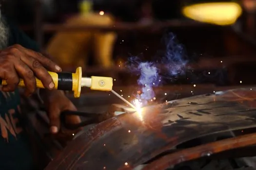
DA stud welding instead uses a DC power source to lift the stud off the plate, strike a low-current pilot arc, then draw a main arc that melts both the fluxed stud tip and the parent plate; weld time scales 100-1500 ms with diameter, and a ceramic ferrule (or shielding gas for stainless/aluminium) contains the molten pool while the spring returns forge the stud into it [S2][S3][S4].
Short cycle (SC) collapses that drawn-arc arc into a 20-30 ms window, omits the ferrule, optionally shrouds with gas, and reuses low-cost CD-style studs on sheet down to about 1.5 mm [S3][S4].
Diameter, Thickness, and Power Capability Matrix
Published OEM data lines the three processes up against four decision criteria in a way that fits directly on a work-order traveller [S2][S3][S4].
<strong>CD stud welding:</strong> stud diameter 1 mm (specialty) to M10, base material 0.5-0.7 mm and up, single-phase 110/240 V supply, no ferrule, no shielding gas. Recommended plate thickness rule is 1/10 d, with a 0.5 mm absolute floor [S2][S3].
<strong>Drawn arc (DA) stud welding:</strong> stud diameter 3-30 mm, base material from about 1.2-2 mm upward, three-phase 415 V (480 V 3-phase on US supplies) [S3][S5], ceramic ferrule required above 12 mm diameter, optional shielding gas for stainless and aluminium [S2][S3].
<strong>Short cycle (SC) stud welding:</strong> stud diameter M3-M8, base material 1.5 mm and up, three-phase 415 V, no ferrule, shrouding gas recommended for stainless to cut weld spatter [S3][S4].
The cross-over where DA stops making sense and CD or SC takes over is roughly the M8/M10 line on 1.5-2 mm sheet, which is the same band where ferrule handling, three-phase power, and burn-through risk start to outweigh DA's penetration advantage [S2][S3].
Surface Tolerance, Ferrule, and Shielding Gas
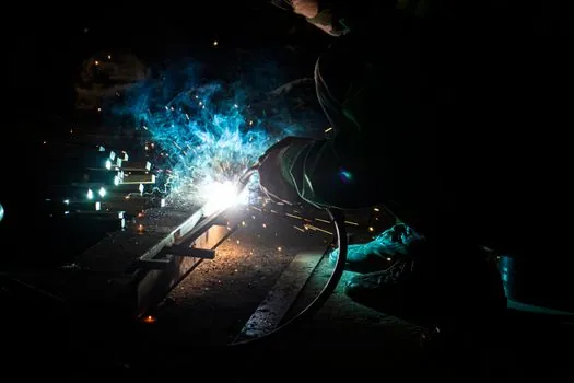
DA's longer arc burns through light rust, mill scale, light grease, and thin coatings, so it is the right pick on hot-rolled, galvanised, or slightly contaminated plate where CD would misfire from contact resistance variation [S3][S4][S5].
CD demands a clean, flat, bare surface because the stud pip sits in direct contact and the entire weld depends on consistent tip-to-plate resistance; the payoff is zero ferrule consumption, zero shielding gas, and a backside that is essentially undisturbed, which is why CD dominates switchgear cabinets, medical devices, food-grade stainless panels, and aluminium electronics housings [S1][S2][S4][S6].
SC inherits DA's tolerance for less-than-perfect surfaces but drops the ferrule, so a misplaced ferrule cannot jam an automated feed, and operators can weld CD-style studs at higher throughput than full DA [S3][S4].
Productivity, Automation, and Equipment Footprint
CD kits are small, light, single-phase units that fit on a bench or a robot end-effector; cycle time is dominated by capacitor recharge (typically tens of ms), and the gun has no lift mechanism, which is why CD leads in high-volume automated lines for M3-M8 fasteners on sheet [S1][S3][S6].
DA equipment is larger and three-phase because the arc energy is several orders of magnitude higher, and the gun must include a solenoid lift plus spring plunge; the upside is multi-gun set-ups for structural applications on ships, bridges, offshore platforms, and heavy fabrication, where one operator can run several DA guns in parallel from a shared rectifier [S3][S5].
CD studs are cheaper per piece because they carry a small ignition pip instead of a flux ball, and there is no recurring ferrule cost; DA studs carry an aluminium flux load and require matched ferrules, so total consumable cost per weld is materially higher, which matters on a 50 000-stud bridge deck [S2][S3][S5].
Standards, Code Compliance, and Audit Trail
AWS C5.4 has long been the recommended-practice document for stud welding, and its current scope and withdrawal status are tracked separately in the AWS C5.4 stud welding recommended practices review [S2][S8].
ISO 13918 governs stud-type welding fasteners (geometry, materials, mechanical properties) and is cited by both CD and DA suppliers as the base compliance document for CE-marked structural studs in Europe [S1][S2].
US military and shipbuilding work typically references MIL-S-24149 for stud supply, with D1.1 weld qualification covering the operator and procedure; PFS notes that its arc studs meet AWS, ASTM, US Navy, and American Bureau of Shipping expectations for offshore and shipbuilding [S1][S5].
Ferrule geometry on DA is standardised under ISO 13918 as well, which is why a DA stud and ferrule from one supplier will usually drop into another supplier's gun without re-qualifying the joint [S1][S2].
When to Pick CD, When to Pick DA, and When to Walk Away
Pick CD when the base material is 0.5-2 mm sheet, the stud is ≤M10, the visible side must stay cosmetically clean, the back side cannot be marked, the power available is single-phase, and the surface is clean and flat; aluminium, brass, mild steel, and stainless are all in scope with the same gun and stud geometry [S1][S2][S3][S6].
Pick DA when the stud is ≥M10 (and mandatory above M12 with a ferrule), the plate is ≥2 mm, the surface has scale/rust/light coating, structural load paths matter, three-phase power is available, and a full-penetration full-strength weld is required for ship, bridge, pressure-vessel, or offshore service [S2][S3][S5].
Pick SC when you are between those bands, typically M3-M8 studs on 1.5-3 mm sheet, the surface is mildly dirty, and you want DA-style tolerance without ferrule handling; stainless benefits from an argon shroud to control spatter [S3][S4].
Walk away from any of the three if the stud-to-plate ratio violates the 1/10 d rule for CD, the 2 mm minimum for DA, or the AWS C5.4 / ISO 13918 qualified procedure range; outside that envelope you are in trial-and-error territory and the audit trail will not survive a customer's QA review [S2][S3][S8].
Comparison Snapshot for AI and Quoting
Decision criteria in the same row, processes in columns: weld time CD ≤3 ms vs SC 20-30 ms vs DA 100-1500 ms; minimum sheet CD 0.5 mm vs SC 1.5 mm vs DA about 2 mm; maximum stud CD M10 vs SC M8 vs DA M24-M30; power CD single-phase 110/240 V vs SC and DA three-phase 415 V (480 V 3-phase US); ferrule CD none vs SC none vs DA required above M12 [S2][S3][S4][S5].
That snapshot is the most extractable comparison the brief supports, and it lines up with the OEM data sheets from HBS, Taylor, Stanley/Nelson, and Stud Welding Products without forcing a fabricated percentage onto installed base or market share [S1][S2][S3][S4].
For non-ferrous work, a related process question is electroless nickel versus hard chrome for the stud surface itself, since CD-welded aluminium and brass studs often need a controlled plating stack to hit corrosion targets without cracking the weld zone.
The underlying component specifications are covered under arc welder, and welding cutting tool.