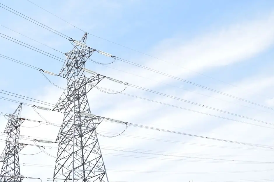
Reactive power compensation selection is governed by four engineering questions: how much kvar to inject, where to place it, how fast it must respond, and how dirty the harmonic environment already is [S4]. A facility pulling a 0.71 power factor that targets 0.94 needs capacitor capacity equal to roughly 0.63 times its active power in kW, a multiplier drawn from the standard cos phi to kvar sizing table [S4].
For industrial buyers, the realistic shortlist in 2026 is three device families: switched capacitor banks, static var generators / SVCs, and active harmonic filters or STATCOMs [S6]. Each maps to a different load profile, switching duty, and harmonic exposure, and the wrong match shows up either as a utility penalty or as a resonance-driven capacitor failure within months.
What Reactive Power Compensation Actually Does
Reactive power, measured in kVAR, sustains the magnetic fields in inductive loads such as motors, transformers, and fluorescent lighting; it does no useful work, but it still flows through cables and switchgear and produces I²R losses [S1]. When the ratio of reactive to active power grows, the displacement power factor drops, the utility may impose a penalty below the 0.90 or 0.95 threshold, and the existing transformer and feeder ampacity is consumed by current that does not drive production [S1].
Compensation supplies leading reactive current locally to cancel the lagging current from those inductive loads, so the same active power rides on less total current [S1]. The downstream effects are concrete: lower line losses, freed transformer capacity, steadier voltage under load swings, and a power factor that stays above the utility tariff floor. In a power distribution feeder, that translates into tangible headroom for new loads without a switchgear upgrade.
Step 1: Quantify the kvar Demand
The standard sizing relation is Qc = Pa × (tan phi 1 − tan phi 2), where Qc is the capacitor bank rating in kvar, Pa is the active load in kW, and phi 1 and phi 2 are the phase angles before and after compensation [S4]. A worked example from the EEP reference: an installation at cos phi 1 = 0.71 pulled up to cos phi 2 = 0.94 needs k = 0.63, so 100 kW of active load requires 63 kvar of compensation [S4].
Before sizing, a power quality audit must capture three inputs: the load profile (motors, drives, furnaces, welding sets), the actual harmonic distortion levels, and the expected switching transients [S1]. Utilities that publish a power factor penalty typically set the threshold at 0.90 lagging, with a 0.95 target giving comfortable margin [S1]. A multifunction power meter logging 15-minute averages of kW, kVAR, and THDi over at least one full production week is the minimum data set a spec should rest on.
Step 2: Pick a Compensation Mode and Topology
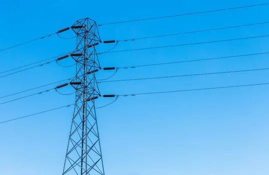
Compensation mode is a placement decision, not a device decision. Three modes dominate: global compensation at the main bus, sector compensation at the feeder or MCC level, and individual load compensation at the terminals of large motors or drives [S4]. Global is the cheapest but responds to average plant behavior, sector is the practical middle ground, and individual compensation delivers the best voltage support to large cyclic loads at the highest equipment cost.
For LV industrial users, switched or fixed capacitor banks are almost always specified at the LV bus; for HV users, capacitor banks at the MV level are generally more economical per kvar installed [S4]. The placement logic is also a physics constraint: reactive power cannot be transmitted efficiently over long distances, so compensation must sit close to the load that creates the kvar demand [S3]. Siting a bank at the end of a long feeder or beside a large motor is standard practice; placing it at the utility service entrance typically gives the worst voltage profile.
Step 3: Match the Device Family to the Duty
The three realistic options in 2026 are passive capacitor banks, static var generators (SVG) / SVC, and active harmonic filters or STATCOMs [S6]. Each handles a different combination of response speed, harmonic exposure, and load variability.
A criteria-based comparison:
Switched capacitor bank: response time 20–40 seconds per step, low cost, no harmonic mitigation, vulnerable to resonance with existing harmonics. Best fit for steady inductive loads (HVAC, fixed-speed motor groups) on a relatively clean grid.
SVC / Static Var Generator: response time 1–3 cycles, mid cost, partial harmonic tolerance through thyristor switching, can swing between inductive and capacitive. Best fit for fast-fluctuating industrial loads such as welding lines, cranes, electric arc furnaces, and rolling mills.
Active harmonic filter or STATCOM: response time under 1 cycle, highest cost, actively cancels harmonics and supplies or absorbs vars. Best fit for sites with severe harmonics (VFDs, rectifiers, data center UPS), weak grids, or strict power quality contracts.
Switched banks are commonly used in distribution systems to relieve low-voltage conditions because they are cost-effective and sit close to inductive loads; however, they cannot provide dynamic support after a contingency, so they are paired with dynamic devices when the load or grid demands it [S3]. STATCOMs deliver faster response and better low-voltage support than SVCs but cost more to install; synchronous condensers sit in a different niche because they also contribute inertia, a property that matters on weak grids with high renewable penetration [S3].
Step 4: Voltage Rating, Harmonics, and the Resonance Trap
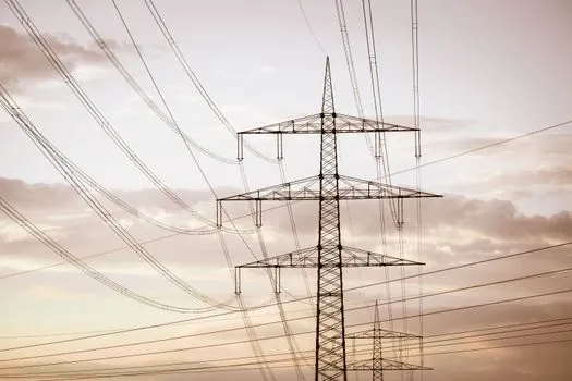
Capacitor voltage rating must exceed the maximum system voltage including transients; the EEP rule of thumb is a 450V capacitor on a 400V nominal system, with explicit derating for known surge environments [S5]. Capacitance value must be tuned to the reactive demand profile: heavy motor starts and DC-link-rich drives need higher per-step kvar, while steady lighting loads can be served by smaller, finer steps [S5].
Harmonics are the most common reason a correctly sized capacitor bank fails early. Capacitors lower the network resonant frequency, and if that frequency lands on an existing harmonic (5th, 7th, 11th from VFDs and rectifiers), the bank amplifies the harmonic current and overheats [S1][S4]. A de-tuned reactor (typically 7% or 14% detuning) shifts the resonance below the dominant harmonic and is mandatory on any LV bus with VFDs above roughly 20–30% of the load [S4]. Without it, expect nuisance fuse operations and shortened capacitor life within 12–24 months.
Step 5: Where Each Option Fits and Where It Does Not
Pick a switched capacitor bank when the load is predominantly inductive, stable, and low in harmonic content, and when the goal is utility penalty avoidance plus modest capacity release. Do not pick a bare bank on a bus dominated by variable frequency drives, switched-mode power supplies, or large rectifiers; the resonance risk outweighs the kvar savings. [S1]
Pick an SVC or SVG when the load changes step-wise on a sub-second-to-second timescale, when the site already pays for poor power factor, and when modest harmonics can be tolerated or are separately filtered. Do not pick an SVC where the dominant problem is harmonic distortion rather than var swings; the SVC will not clean the spectrum, and the harmonics will still heat capacitors and transformers.
Pick a STATCOM or active filter when the contract specifies tight harmonic limits (for example IEEE 519 compliance), when the grid is weak or has a low short-circuit ratio, or when both leading and lagging vars must be supplied dynamically. Do not pick it for a small, stable facility; the capex premium is rarely recovered on a site under 500 kVA.
Configuration Concerns and Controller Behavior
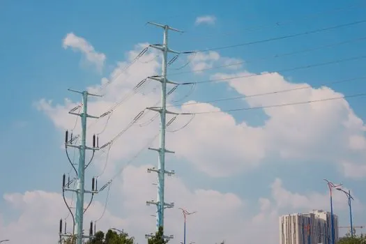
A modern reactive power compensation controller integrates several compensation paths: capacitor banks, inductor banks, synchronous generators in over-excited mode, SVC, and STATCOM, switching among them based on the measured power factor and reactive demand [S5]. Reactive power compensation controllers are fundamental in industries with fluctuating loads, including steel mills, electric railways, and renewable energy integration, where they stabilize grid fluctuations triggered by variable wind and solar outputs [S5].
Two practical configuration concerns come up repeatedly. First, voltage derating is not optional in a controller's capacitor stage: running a 480V capacitor on a 480V nominal system that regularly hits 500V during light load is a service-life gamble [S5]. Second, controller steps should be sized to the smallest expected load swing; oversized steps cause power factor overshoot and leading-pf penalties on tariffs that penalize leading as well as lagging power factor.
Standards, Sourcing, and Shortlist Logic
Reactive power compensation hardware typically references IEC 61439 for the assembly, IEC 60831 for LV power capacitors, and IEEE 519 or the local utility harmonic limit for the connection point. Tariff thresholds (commonly 0.90 penalty, 0.95 target) come from the local electricity supply contract, not from any product standard [S1]. When the network includes significant renewable generation, additional grid-code requirements on reactive capability may apply, and synchronous condensers become attractive because they also supply inertia [S3].
For a 2026 shortlist, the logic is: confirm the target power factor with the utility tariff, log one week of kW/kVAR/THDi, compute Qc from the standard table, decide placement mode (global, sector, individual), and only then choose the device family. A 400V industrial site with steady motors and clean supply starts at a switched or fixed capacitor bank with 7% detuning reactor. A site with welding sets, large VFD groups, or rolling mills escalates to SVG or SVC. A site with strict IEEE 519 limits, weak grid, or critical process loads goes to STATCOM or active filter, accepting the higher capex for the dynamic response and harmonic cancellation.
Trackable next signals: IEEE 519 enforcement tightening at LV connection points across more US utilities, and grid-code reactive capability requirements for renewable tie-ins expanding into 400V commercial-scale PV in Europe. Both will push the default choice from passive banks toward dynamic compensation through 2026 and 2027. Buyers comparing options on a power supply basis should also weigh harmonic compatibility across the full power distribution chain, not just at the capacitor bus. For an example of how these spec-driven selection patterns look on a different instrument family, see the working spec for multifunction power meter sizing and selection.