
A conveyor cell's power transformer is sized to 1.25-1.5x the connected motor kVA sum to absorb locked-rotor inrush, with a Dyn11 vector group as the default for European and Indian cell builds where line-to-ground isolation and harmonic-rich VFD loads dominate [S1][S2].
The decision is bounded by four hard numbers: continuous kVA headroom, impedance (%Z) window, insulation temperature class, and short-circuit withstand — each testable on the manufacturer's routine-test report rather than on marketing copy.
Step 1 — Quantify kVA Demand and Headroom
Add the nameplate kW of every motor, VFD, brake, heater and control PSU on the cell, divide by 0.85-0.9 to recover realistic motor power factor, then apply a 1.25 multiplier for non-simultaneous duty or 1.5 for a duty cycle with frequent starts and stops [S2]. Industrial cell-build practice treats 25-50 % continuous headroom as the engineering floor — pick the next standard rating above that figure to avoid operating in the knee of the loss curve. Below 5 kVA the same math still applies, but a UL 5085-1 Class 2 split-bobbin construction such as Triad's F16-150-C2 (2.5 VA, 115 V primary, dual 8 V @ 0.15 A secondaries, 25 % voltage regulation typical) is the accepted control-transformer form [S3].
Step 2 — Pick the Vector Group Before kVA
Vector group selection sits ahead of physical sizing because it locks in fault-isolation, paralleling compatibility, and harmonic behaviour [S1]. Dyn11 is the default in 400 V European cells and 415 V Indian cells because the delta primary blocks triplen (3rd, 9th, 15th) harmonics from VFD rectifiers and supplies a neutral on the secondary for single-phase auxiliaries [S1][S2]. Yyn0 is acceptable only on a clean, linear, balanced load with no VFDs; on a VFD-fed cell it lets zero-sequence harmonics return into the primary and distorts the upstream bus. For two transformers that must parallel on either side, the vector group must match exactly and the phase displacement must be identical, otherwise circulating current flows even at no load.
For an isolation duty with a converter or inverter load, the Dyn vector group is the textbook choice: the delta provides a closed circulating path for third-harmonic currents and isolates triplen noise from the upstream grid, while the wye secondary gives a neutral for 230 V single-phase auxiliaries drawn off the same transformer [S1].
Step 3 — Set the %Z Window Against Fault Current and Voltage Dip

Impedance (%Z) is the single number that ties upstream breaker coordination to downstream motor starting. For a 50-500 kVA cell transformer, 4-6 %Z is the standard industrial window; below 4 %, the let-through fault current at the 400 V bus may exceed the breaking capacity of moulded-case breakers (typical 25-36 kA frames become marginal above ~50 kA prospective). Above 6-7 %, the voltage dip on a direct-on-line motor start gets long enough to drop contactors out — most 400 V contactors drop out below 70 % nominal. Match the cell's largest motor's locked-rotor kVA to roughly 0.6-0.8 of the transformer's short-circuit kVA so the dip stays inside 15-20 %. [S3]
Step 4 — Insulation Class, Cooling, and Ambient
Class F (155 °C) windings with 40 °C maximum ambient and 80 °C average winding rise is the default for indoor conveyor cells; Class H (180 °C) is reserved for cells next to furnaces, in enclosures without forced ventilation, or where the transformer feeds a long cable run with poor power-factor correction. Dry-type cast-resin construction (epoxy-encapsulated) is now the default indoors because it eliminates the oil containment pit and meets the lower fire-load requirements of food, pharma and packaging cells [S2].
For an outdoor or dust-heavy cell (cement, grain, foundry) the conservative pick is a sealed oil-immersed unit with a hermetically sealed tank, conservator-free design, and a breather fitted with silica gel; the same duty built dry-type needs a IP54 enclosure and a derating curve (typically 0.5-0.7 of nameplate above 45 °C ambient). Reference the manufacturer's derating curve against the cell's worst-case ambient, not the controlled-room value on the layout drawing.
Step 5 — Compare Realistic Options for a Cell Duty
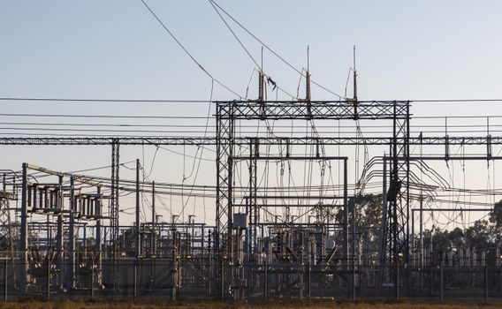
Three options dominate conveyor-cell purchasing, each with a distinct cost/lead-time/runtime profile. Control-class split-bobbin (CL2) single-phase or 3-phase, 0.05-5 kVA, UL 5085-1 Class 2/3: cabinet-mounted, inherently current-limited, no fusing required, stock-item lead time, used only for the control and instrumentation secondary, never for motor power [S3].
Decision rule: pick CRDT for an indoor packaging or assembly cell with a tight floor plan and a 1-2 month install window; pick OIL for an outdoor bulk-handling or quarry cell where a 25-year service life outweighs install speed; pick CL2 strictly for the control transformer inside the cell's MCC panel, sized to the inrush of contactors and relay coils, never to the conveyor motor.
Step 6 — Verify Routine-Test Numbers on the Nameplate
Five datasheet numbers must be on the test report before a unit is accepted: no-load loss (W), load loss at 75 °C (W), impedance voltage (%) measured, sound level (dB(A) at 1 m), and temperature-rise test result. Industrial cell-build practice is to reject any unit whose measured %Z deviates more than ±10 % from the declared value, whose no-load loss is more than 15 % above catalogue, or whose temperature rise exceeds Class F 100 K at 1.0 pu loading [S2].
Also confirm the dielectric test (separate-source voltage withstand, typically 3-5 kV/1 min for ≤ 36 kV class) and the induced-voltage test on the report, not just the type-test certificate from a catalogue cut. For a Class 2 control transformer such as the F16-150-C2, the equivalents are hipot at 4200 VRMS primary-to-secondary and 2160 VRMS secondary-to-secondary at 100 % production test, with UL 5085-1 / -3 (CSA 22.2 No. 66.3-06) as the governing standard [S3].
Who Should Not Pick the Default (Dyn11, 6 %Z CRDT)
Skip the default if the cell feeds a large single motor above 75 % of transformer kVA at direct-on-line start, if the upstream system already carries heavy DC ripple from another rectifier load, or if the cell sits on a generator bus where sub-transient reactance and transformer reactance add. In each of those cases drop to 4.5 %Z or add a soft-starter / VFD on the largest motor to keep the dip under 15 %. Also avoid cast-resin in cells where ambient exceeds 50 °C for sustained periods, where altitude exceeds 1000 m without derating, or where the duty cycle has > 60 starts/hour — the resin encapsulant is the thermal bottleneck, not the winding copper. [S1]
For cells with high harmonic distortion from VFDs, specify either a K-rated transformer (K-factor 4 or 13) or a true harmonic-mitigating design with a dual-output or phase-shift winding; a standard Dyn11 unit will run hotter than its nameplate predicts because eddy losses in the windings scale with harmonic current squared.
Sources, Standards and Trackable Signals
Apply IS / IEC / ANSI standards to test reports rather than to brochures, and require the manufacturer's ISO 9001 certificate scope to cover the actual production line, not a separate division [S2]. UL 5085-1 / -3 (CSA 22.2 No. 66.3-06) governs Class 2 / 3 control transformers up to roughly 5 kVA, with 155 °C (Class F) insulation and 25 °C typical rise for low-VA units [S3]. The vector-group decision itself is engineering judgement, but the four-bullet checklist — line-to-ground fault isolation, paralleling compatibility, harmonic isolation, and load type — is the standard Q&A reference and remains the engineer-side answer for any audit [S1].
For spec-first guidance on adjacent MCC hardware, the related panel-builder wiring duct map covers cable-routing density for the same cell, the LV power distribution box spec map covers the downstream distribution side, and the modular UPS spec gates cover ride-through for VFD control supplies. Reference the power transformer encyclopedia entry for the full vector-group and impedance reference set. Next signal to watch on 2026-08-04: the kVA-weighted price index for 11 kV / 0.433 kV Dyn11 cast-resin units at 100-500 kVA, and the publish date of the next IS 1180 amendment for distribution-transformer short-circuit withstand.
The underlying component specifications are covered under load cell, and load cell module.