A modern crystalline-silicon solar panel is built from eight sequential steps — cell tabbing and stringing, string bussing, layup, EL inspection, lamination, framing, junction-box welding, and final IV/flash test — and each step is a separate machine on a turnkey line [S1][S5].
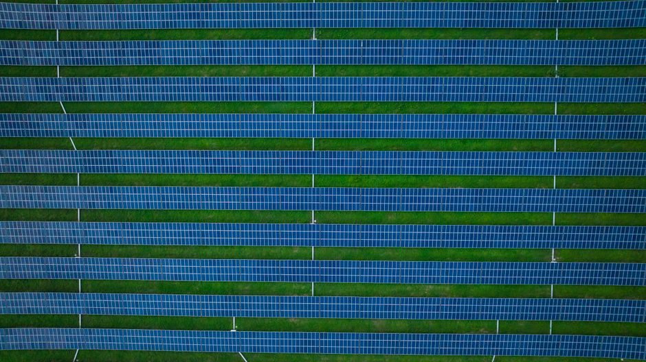
Off-the-shelf production capacity tiers from Chinese turnkey builders start at 5MW/year, jump to 10MW, 20MW and 30MW reference packages, and scale up to 200MW, 400MW and 600MW annual output, with 10–30MW turnkey packages quoted in the USD 200,000–300,000 range [S3][S5][S7].
Stringing, Bussing and Layup: Where the Module Is Physically Born
Tabber-stringers weld flat copper ribbon (typically 1.0–1.5 mm wide) onto cell busbars at roughly 6–12 cells per minute per lane, and downstream bussing machines series-connect the ribbons from adjacent strings to form a 60- or 72-cell electrical circuit [S1]. Cell-to-cell spacing is held to a few millimetres to control module dimensions and the eventual laminate void pattern.
Full-automatic layup stations then place the string array face-down on a tempered low-iron glass sheet, lay an EVA encapsulant sheet on top, place the cells, add a second EVA layer and a PET/TPT/TPE backsheet, and route the lead wires to where the junction box will be potted [S1][S3]. Layup is the highest human-touchpoint step on a brand-new line; even a 200MW line typically uses semi-automatic layup before scaling to full-auto cells.
EL Inspection, Lamination and the Thermal Envelope
Pre-lamination electroluminescence testers image every cell at ~1–5 A forward bias using a cooled InGaAs or Si CCD camera, catching microcracks, broken fingers, and tab-ribbon misalignment before the panel is sealed — defective cells reworked at this stage cost cents; defective laminates cost dollars [S1]. A full-auto in-line EL station is standard on any line rated 30MW and above.
Laminators run a vacuum-and-press cycle: vacuum hold to remove air, then a cure plateau at roughly 140–160°C for 8–15 minutes that crosslinks the EVA encapsulant, followed by a controlled cool-down, all under pressure to suppress bubbles [S1]. Ooitech and Reoo both offer double-chamber and multi-opening laminators sized to the line throughput, and cycle time is the line's true bottleneck — a 30MW/year output roughly needs 2–3 laminator cavities running 8–12 cycles/shift [S5][S7].
Framing, Potting and the Final Test Set
Solar panel framing machines dispense sealant, press anodized aluminium profiles (typically 30–35 mm height) around the laminate, and corner-crimp or screw the joints; junction-box welding stations then attach the IP67/IP68 J-box and pot it with silicone [S1]. For modules targeting 1500V system voltage, the J-box and diode rating must be specified accordingly — a 1500V-rated diode block is not the same BOM item as a 1000V part, and this is a frequent spec trap on cheap lines.
Final test is a flash tester (class A or AA AAA pulsed solar simulator) plus a hi-pot / insulation withstand test and an EL re-inspection on the finished module to confirm lamination did not introduce new cracks [S1]. Acceptance bands published on datasheets — Voc tolerance ±3%, Isc ±3%, Pmax 0 to +3% — are measured at STC: 1000 W/m², AM1.5G, 25°C cell temperature.
Line Sizing and Per-MW Capex for 2026 Buyers
Capacity tiers scale roughly with workshop area and capex: 5MW/year is the entry-level semi-auto build, 10–30MW is the standard turnkey package, 200MW is a serious fab floor, and 400–600MW is the upper band quoted by Ooitech for a greenfield PV module plant [S5][S7]. Reoo's 10MW/20MW/30MW turnkey packages list in the USD 200,000–300,000 per-line band, which works out to a fraction of the unit capex seen on 200MW+ builds [S3].
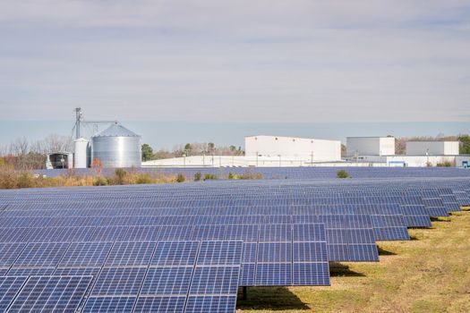
Raw materials pulled into a 1MW production run include roughly 8,000–9,000 monocrystalline cells, 500–600 m² of tempered low-iron glass, comparable metres-squared of EVA and PET backsheet, 50–60 km of tinned copper ribbon, and framing aluminium in the 18–22 t range [S3]. Buyers should size the layup, lamination and framing stations together — a 10× bump in layup throughput with the original laminator turns into queue, not capacity.
Process Choices and Where Lines Differ
Topcon, HJT and PERC lines diverge mainly at the cell side (upstream of the tabber-stringer), but at the module side the equipment list — tabber, busser, layup, EL, laminator, framer, J-box welder, flash tester — is essentially identical for mono and multi lines up to 200MW [S4][S6]. What changes is the lamination thermal budget: HJT cells with amorphous-silicon passivation layers are more temperature-sensitive than PERC, so the cure plateau stays toward the lower end of the 140–160°C window and cycle time stretches accordingly.
For 2026 sourcing, the practical decision tree is short: confirm cell technology (PERC/Topcon/HJT) and laminate size (M6/M10/G12 wafer, 60/72/120-cell layout), then size line capacity at 5/10/20/30/100/200/400/600MW tiers, then lock the BOM for ribbon, encapsulant, glass, backsheet, frame, J-box and silicone against IEC 61215 and IEC 61730 long-term test data. The wider question of how a process line is built, gated and sourced is mapped step-by-step in this [transformer manufacturing process reference](/news/transformer-manuring-process-five-stage-build-chain-spec-gates-and-2026-sou.html), and the cell-to-pack automation logic for an adjacent industry looks similar in this EV battery smart manufacturing breakdown. For plants that already host rooftop PV, the BIPV envelope and roof-mounting spec cut sits one step downstream of the module.
Trackable signals for the next sourcing cycle: tabber-stringer throughput per lane (cells/min), laminator cycle time and cavity count, flash-tester class (A vs AA vs AAA), and J-box 1500V certification status [S1][S5][S7].
For component-level specifications, see alc panel, hmi panel, and aluminum veneer panel.