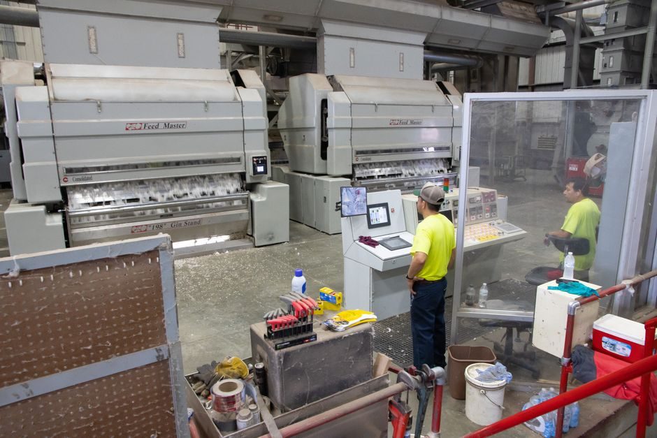
A DC fast charger is engineered around three functional blocks: a unity-power-factor front-end AC/DC converter that lifts three-phase grid power to ≈800 V DC, an isolated high-frequency DC/DC stage that regulates constant current into the EV battery, and a communications/control layer for ISO 15118, OCPP and PLC signalling [S3].
Production bands observed on shipping product span 50 kW (EVBox Troniq 100, CHAdeMO + CCS2 + AC Type 2) up to 360 kW all-in-one cabinets such as the Nidec DirectPowerPS that share one or two CCS1/NACS outputs through dynamic power balancing [S5]. The 2026 line mix is dominated by SiC-based power integrated modules that collapse three discrete stages into a single PIM, which is what makes liquid-cooled 350–400 kW units manufacturable in a 1.2–1.8 m cabinet footprint [S6].
Front-end AC/DC stage: SiC modules and unity power factor
SiC power integrated modules replace the IGBT + Si FRD stack of a previous-generation 50 kW charger and cut rectifier-stage losses by roughly half, which is the primary thermal lever that lets 25 kW units move to fan-cooled enclosures and 150–360 kW units move to closed-loop water cooling [S6].
The front-end converter is specified as a unity-power-factor FEC that holds the internal DC bus at 800 V regardless of line variation; MathWorks models used for firmware validation expose average-value, two-level and three-level inverter fidelities so control engineers tune PWM, Park transform and DC-link voltage loops against three-phase supply perturbations before silicon is touched [S3]. ABB's Terra 94/124/184 family covers the highway segment with both single-outlet CCS and dual-outlet CCS+CHAdeMO configurations sharing one FEC, illustrating how a single rectifier design is reused across 94 kW, 124 kW and 184 kW output ratings [S2].
Isolated DC/DC conversion and high-frequency transformer block
The isolated DC/DC stage runs at high switching frequency, steps the 800 V bus down to the EV pack voltage window, and uses an HF isolation transformer plus a diode-bridge or synchronous rectifier to deliver constant charging current under closed-loop control [S3].
For 800 V-pack vehicles, the DC/DC stage must regulate continuously from ≈200 V to 920 V output while sustaining 400–600 A on liquid-cooled dispensers; this is the block that scales with kW rating, not the front end. ABB's 184 kW C-variant reaches that band by paralleling DC/DC converter modules behind one FEC, while 360 kW cabinets such as the DirectPowerPS allocate the full rectifier capacity to a single CCS1 or NACS/J3400 connector in SOLO mode or split it dynamically from 120 kW to 360 kW across two vehicles in DUAL mode [S2].
Cooling, IP-rated enclosure and dispenser cabinet assembly
Charger enclosures are typically stainless or powder-coated steel cabinets rated IP54–IP65 for outdoor sites, with separate compartments for the power module stack, the filter/suppression board, the AC input breaker panel, and the user interface; NEMA 3R/IP54 is the de-facto retail spec and IP65 is common for highway pull-through sites. [S1]
Liquid-cooled dispensers route a 50/50 propylene-glycol-water mix through cold plates bolted to the SiC modules, which lets manufacturers shrink the cabinet depth by 30–40% versus forced-air designs at the same power level [S6]. CCS1, CCS2, CHAdeMO and NACS/J3400 connector assemblies are sourced as pre-certified cable harnesses (typically 5 m or 7 m, with liquid-cooled variants carrying 250 A continuous and 500 A peak), and the holster, cable management arm and credit-card/PIN reader are kitted as a sub-assembly that is bolted to the cabinet door before final line integration [S2].
Communications stack: ISO 15118, OCPP and the controller layer
Every modern DC fast charger carries a service controller that speaks OCPP 1.6/2.0.1 to the back office, ISO 15118 (and DIN SPEC 70121 for backward compatibility) to the vehicle over Power-Line Communication, and supports features like Autocharge, Plug & Charge, and PIN-on-terminal authentication [S2].
The communication hardware is a Linux-class SBC with an isolation transformer for the PLC coupler, a 4G/Ethernet modem, and a touchscreen HMI; ABB's Terra family ties all of this together with Web Tools for commissioning and optional credit-card readers for ad-hoc payment [S2]. Inside the cabinet the control PCB talks to the SiC module gate drivers over CAN or SPI, and a separate metering board carries the DC kWh meter required for billing — that meter is calibrated and sealed separately from the power electronics and is a distinct end-of-line test step.
End-of-line test, type-test and site commissioning
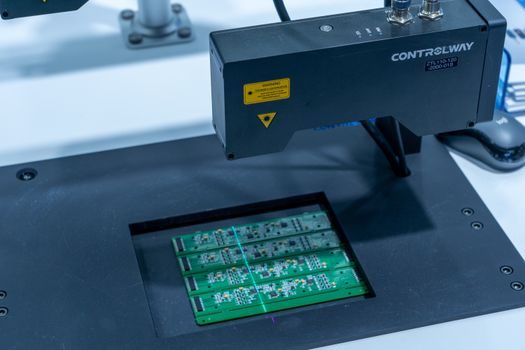
End-of-line test on a 2026 line runs through four gates: hipot/insulation resistance at 2.5 kV AC plus 1 kV DC on the isolation transformer; a no-load power-on that verifies the FEC reaches 800 V DC bus and the controller boots ISO 15118 within 90 s; a load-bank burn-in at rated kW for 30–60 minutes; and a CHAdeMO/CCS/NACS plug-cycle test plus OCPP handshake against a server simulator [S3][S6].
Type-test for the whole cabinet adds EMC to IEC 61000-6-2/6-4, surge to IEC 61000-4-5, environmental to IEC 60068, and a short-circuit / ground-fault test that is duplicated in the Simulink fault library used during firmware validation [S3]. Reference designs such as the onsemi 25 kW EliteSiC PIM charger are released as a complete schematic + firmware + test-fixture bundle so contract manufacturers can build a working line without re-deriving the EMC stack [S6].
Selection criteria and where DC fast charger lines do not fit
Selection of a 2026-era DC fast line comes down to four criteria: output power band (50/120/150/180/240/360/400+ kW), connector portfolio (CCS1, CCS2, NACS/J3400, CHAdeMO), cooling architecture (air-cooled up to 150 kW, liquid-cooled above 200 kW), and back-office protocol (OCPP 1.6J vs OCPP 2.0.1 with ISO 15118-20 Plug & Charge) [S2][S5].
Comparison across the dominant topologies: air-cooled discrete-IGBT is the cheapest at ≤50 kW and is acceptable for depot and retail installs, but cabinet volume and audible noise are the gating limits; SiC PIM with forced-air cooling covers 50–150 kW with the best cost per kW; SiC PIM with closed-loop liquid cooling covers 200–360 kW and is the only practical way to hit 350–400 kW highway specs; and modular stacked DC/DC stages (as in the Terra 94/124/184 family) cover the 90–200 kW mid-band by paralleling identical 30–60 kW bricks behind one FEC [S2][S6]. A DC fast line is not the right pick for 7–22 kW home or workplace duty — that market belongs to AC wallboxes built around an additive manufacturing material-style enclosure supply chain and a single-phase dc power supply module, not a three-phase SiC stack.
Manufacturing process flow and process-control signals
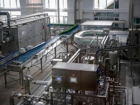
The bill-of-process for a 50–360 kW charger runs through: cabinet sheet-metal fabrication and powder coating, power-module PCBA (SMT + selective soldering for through-hole bus bars), isolation transformer winding and vacuum impregnation, harness and coolant-loop assembly, sub-assembly integration, software flashing and MAC/IP provisioning, four-stage EOL test, and pack-out with shipping skid [S4][S6].
Key process-control signals that show a line is mature are HIPOT pass-rate above 99.5%, EOL burn-in ΔT below 5 K across the SiC baseplate, OCPP handshake success above 99% on first power-up, and field failure rate below 0.5% in the first 90 days. For adjacent context, the parallel shift to smart manufacturing on EV-charger lines — OCPP-integrated test cells, liquid-cooled DC end-of-line rigs, and 2026 capacity announcements — is mapped in this EV charger smart manufacturing roundup, and the upstream power-electronics module lines feeding those plants share many of the same SiC PIM test fixtures described in this Industry 4.0 GPU-process-plant spec sheet. For the enclosure and cabinet side, the welding and robotic-assembly playbook overlaps with EV traction-motor smart manufacturing lines that share the same power-conversion test cells.
Track the next node as ABB's 2026 Terra HP 400 kW platform ramps, which moves the FEC bus from 800 V to 1000 V and forces a second-generation HF transformer; on the component side, watch onsemi and Infineon SiC PIM second-source qualification — only two qualified SiC sources today keep the line BOM constrained even when cabinet volumes are not. Inside the cabinet, the dc-dc converter block is the bottleneck stage for both yield and field reliability, since the isolated HF transformer is hand-wound on most lines and a single void in the epoxy impregnation shows up as a six-month field failure.