An e-axle integrates a Buried-Permanent-Magnet Synchronous Machine (BPMSM), a SiC-based inverter, and a high-speed transmission into a single housing, with a typical A-segment reference target of 800 V fast-charge compatibility via an intermediate DC/DC stage [S3].
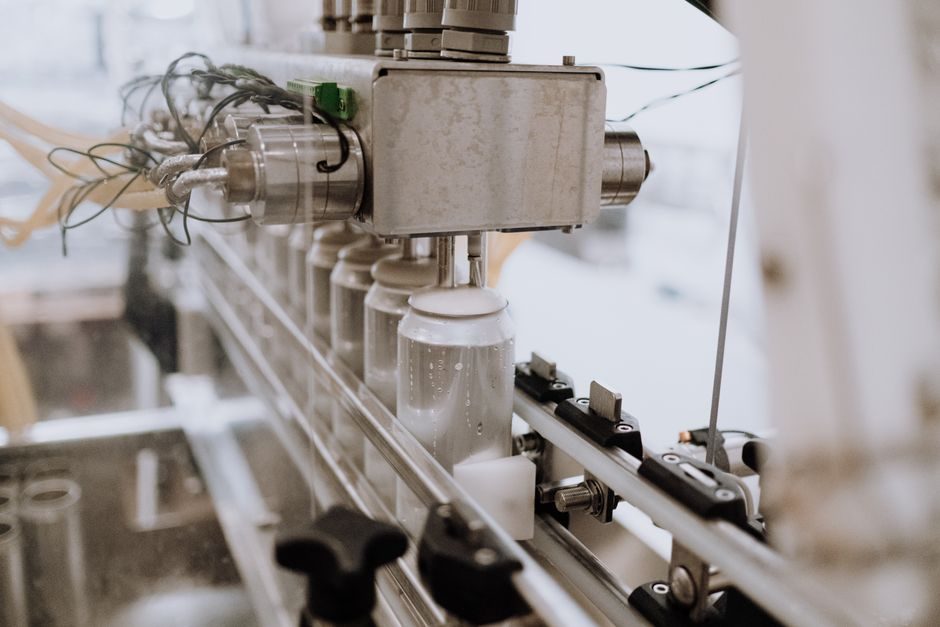
Manufacturing spans four process families — rotor/stator winding and magnetisation, gear cutting and heat treatment, inverter PCB/power-module assembly, and final e-axle integration — and tier-1 suppliers such as AISIN now run multiple eAxle product variants on a single flexible line by separating model-common processes from model-specific cells [S5].
Structural Components and Their Manufacturing Implications
An e-axle for commercial EVs combines a centralised motor, coaxial or parallel reduction gearbox, and a half-shaft that transmits torque to the wheel hub; Brogen's component breakdown lists e-Beam (M/T-Series), Coaxial (M-Series), Distributed Drive and Electric Portal Axle architectures as the dominant layouts for LCV, truck and bus applications [S2].
The half-shaft type governs the process route: full-floating shafts carry only torque and are typically produced as forged-and-machined alloy-steel bars, while semi-floating designs must additionally carry wheel-induced loads, restricting their use to passenger cars and light commercial EVs where cost and lightweighting take priority [S2].
Half-Shaft Materials, Heat Treatment and Machining Sequence
Common e-axle half-shaft materials are 40Cr and 42CrMo high-strength alloy steels; both are specified because their hardenability supports through-section quenching at the spline and journal diameters that see peak torsional and bending stress [S2].
The standard heat-treat sequence is quenching followed by tempering, which lifts tensile strength, impact toughness and wear resistance simultaneously — a combination that as-rolled or as-forged 40Cr/42CrMo cannot reach, so most suppliers treat the rough-machined shaft before final spline rolling and grinding [S2].
Machining typically runs forging → rough turning → heat treatment → finish turning → spline rolling/ hobbing → grinding → dynamic balancing; the final balance step matters because e-axle NVH targets are tighter than ICE axle targets due to the absence of engine masking noise.
Gear Cutting, Hard Finishing and NVH-Critical Tolerances
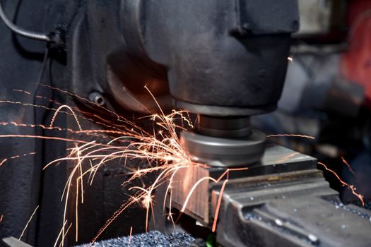
E-axle reduction gears are usually case-hardened alloy steels (16MnCr5, 20MnCr5, or 8620H equivalent) machined by hobbing or skiving, then finished by gear grinding or hard skiving to reach the ISO 1328 accuracy bands (commonly 6-7 for passenger EV, 5-6 for NVH-sensitive NVH programmes) required when input speeds exceed 15,000 rpm on single-speed e-axles. [S1]
Press-quench simulation and flank-line micro-geometry corrections are applied to the pinion because BPMSM torque ripple couples directly into gear-mesh excitation; the SiC inverter's high switching frequency leaves the gearset as the dominant mechanical NVH source in the integrated unit [S3]. For prototype pinion blanks, some suppliers trial additive-manufactured alloy materials before committing to a case-hardened 16MnCr5/20MnCr5 production route.
Rotor and Stator Build for the BPMSM
The traction machine inside the FITGEN reference e-axle is a Buried-Permanent-Magnet Synchronous Machine, paired with a SiC inverter and high-speed transmission; the magnet-embedding step (inserting pre-formed NdFeB segments into laminated rotor slots or rotor pockets) replaces the surface-mount glue path used on earlier PMSM rotors and tolerates higher rotor surface speeds. [S2]
Stator builds use hairpin or wave winding with paper/continuous-fibre slot insulation; the winding process is followed by a dip-and-bake or direct-cooling impregnation step to manage partial-discharge inception voltage under SiC-inverter fast dv/dt, and AISIN's flexible line is designed to switch stator-lamination stack heights without retooling the cell [S3][S5].
SiC Inverter and Power-Electronics Assembly
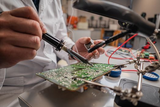
The inverter section uses silicon-carbide MOSFET power modules because SiC's lower switching losses support the 800 V bus that the FITGEN deliverable specifies; a 400 V on-board battery pack can still be fast-charged at 800 V stations through the intermediate DC/DC stage, which is itself a high-frequency planar-transformer assembly [S3].
Power-module production pairs silver-sinter die attach (replacing solder for higher thermal-cycling endurance) with aluminium-wire or copper-clip bonding; AVL's e-axle production test systems then run end-of-line inverter test that combines HiPot isolation, gate-driver waveform capture and torque-speed mapping against a dyno-loaded e-axle [S6]. The inverter cooling loop is typically instrumented with pressure transmitters and flow meters to verify coolant delivery before the loaded efficiency sweep.
Flexible Line Architecture: Cell-and-Line Hybrid
AISIN's cell-and-line hybrid production system consolidates processes common across eAxle models into automated cells, while keeping model-specific operations on parallel lines; the result is a single physical line that can run multiple product variations efficiently without sacrificing cost competitiveness [S5].
The same cell-and-line model fits the broader EV-component industry pattern: as one AVL commentary frames it, the demands for industrialisation and production volumes in e-mobility are rising in parallel, and end-of-line testbeds must cover motor, inverter and gearbox behaviour together rather than as three separate stations [S6].
For battery-pack makers evaluating similar production moves, the battery pack manufacturing process flow provides a useful comparison for cell-to-pack topology, module assembly and QA stack design choices. Process engineers mapping automation across adjacent clean-energy lines can also reference the Industry 4.0 reference for GPU process plants to align e-axle cell-and-line investments with broader plant-side digital-twin requirements.
Production Testing and End-of-Line Quality Gates
End-of-line test for an e-axle typically includes partial-discharge and HiPot on the stator winding, no-load back-EMF and short-circuit phase-balance check, inverter insulation resistance, NVH run-up at rated and overspeed, and a loaded efficiency sweep across the torque-speed map; AVL groups these into an E-Axle Production Test System that synchronises dyno, inverter and gear-stage data acquisition in one station [S6]. The test-cell sensor suite is normally validated by a multifunction process calibrator against traceable torque, current and pressure references before each production shift.
Process engineers specifying test capacity should size the loaded run to cover both the SiC inverter's continuous rating and its peak overload (typically 2-3× continuous for ~10-30 s traction events), because partial-load efficiency mapping alone does not catch thermal-fatigue defects in silver-sintered die attach.
Selection Criteria by Application Segment
E-axle architecture choice is driven by torque, packaging and cost: an Electric Portal Axle suits low-floor buses where wheel-end space is generous, a Coaxial M-Series suits trucks needing high torque density in a compact package, and a Distributed Drive layout suits heavy-duty applications where redundancy matters more than integration density [S2].
For half-shaft selection, full-floating shafts fit trucks and buses (high torque, semi or full trailer loads), semi-floating shafts fit LCV and passenger EVs (cost- and weight-driven), and a quenched-and-tempered 40Cr shaft is the default unless fatigue life at the spline root demands the higher hardenability of 42CrMo [S2].
Trackable next signals to watch: published cycle-time benchmarks for cell-and-line hybrid eAxle lines as second-generation programmes ramp; wider adoption of silver-sintered SiC power modules in e-axle inverters; and the publication of 800 V fast-charge conformance test profiles that the FITGEN architecture was designed against [S3][S5][S6].