
A DC fast charger is a high-power EV charging station that delivers direct current to the battery directly, bypassing the vehicle's onboard AC converter, with most commercial units rated between 50 kW and 350 kW [S2]. Manufacturing these units is a multi-stage process that links power-electronics design, mechanical fabrication, and OCPP network integration, and U.S. operators had ~15,000 DC fast charging station locations and 72,000 DC fast charging ports deployed as of May 2026 [S5].
The core build centres on three subsystems: an IGBT/MOSFET-based rectification and PFC front end, a DC/DC conversion stage, and a control board running OCPP plus 4G/Ethernet backhaul [S4]. Connector choice (CCS, CHAdeMO, NACS, GB/T) and the enclosure's IP rating are not options but spec gates, since site operators require UL/IEC compliance and at least IP54 outdoor protection to keep the warranty path open.
Power Range, Connector Mix, and What "Fast" Actually Means
Commercial DC fast chargers (Level 3) operate between 50 kW and 350 kW and can move a modern EV from 20% to 80% state of charge in roughly 15-40 minutes, depending on the charger's rated power and the vehicle's acceptance curve [S2]. Tesla's Supercharger architecture runs at 480 V DC and is rated to add ~200 miles of range in 15 minutes, while the Wall Connector variant is a 44 mph Level-2 unit, not a DC fast product [S3].
Siemens' Sinamics DCP line covers 200-920 V DC output at up to 200 A from a 380-480 V AC supply, illustrating the wide output window needed to support both 400 V and 800 V battery architectures from a single cabinet [S3]. Connector proliferation is now the rule, not the exception: CCS1, CCS2, CHAdeMO, NACS, and GB/T all coexist, and OEM cabinets must accept either dual-connector or swappable-cable layouts to cover North American, European, and Chinese vehicle populations on the same production line.
Power Electronics Stack: Rectification, PFC, DC/DC
The system architecture is built around three functional blocks: an active rectifier/PFC stage, an isolated DC/DC converter, and a control board handling CAN/PLC communication to the vehicle [S4]. Switching devices (IGBTs at the 50-150 kW level, MOSFETs or SiC at higher power densities) are paired with film and electrolytic capacitors, toroidal or planar inductors, and pre-charge resistors sized for the DC-link capacitance.
Thermal management is the dominant reliability gate: liquid cold plates are now standard above 150 kW, while forced-air heat sinks remain acceptable for 50-100 kW wall-mounted units. A DC-DC converter stage is the single most failure-prone subsystem, since it carries full output current at the lowest efficiency in the chain, and BOM selection (SiC vs. IGBT, dry-film vs. liquid cooling) directly drives MTBF. For OEM test stands, a programmable DC power supply sourcing 600-1000 V at full rated current is mandatory for end-of-line verification before shipment.
Mechanical Build: Enclosure, IP Rating, and Cable Management

Enclosure dimensions and internal layout are defined by installation mode (wall-mounted, pedestal, or containerised) and the required IK/IP rating; outdoor highway-corridor units typically target IP54 minimum and IK10 for vandal resistance [S4]. Sheet-metal fabrication uses laser-cut cold-rolled steel or marine-grade aluminium, with powder-coat or anodised finish, and internal sub-frames are designed around service access for the linear guide rails that slide the power module out for field service.
Coolant manifolds, busbars, and high-voltage harnessing are routed with defined creepage and clearance per IEC 60664, while the charging-cable management system (retractor, swing arm, or fixed holster) is tested to 10,000+ mating cycles to match connector durability ratings. Cabinet ventilation, particulate filters, and condensation heaters are integrated for sites below -10 °C, where NACS and CCS spec minimums push the cold-start design window down to -30 °C on premium units.
Software, OCPP, and Network Backend
Control software is developed alongside the hardware BOM and includes the OCPP 1.6J or 2.0.1 stack, ISO 15118 (Plug & Charge) handling, and 4G/Ethernet communication modules for backend telemetry [S4]. CyberSwitching's commercial DCFC line, for example, ships with native ISO 15118 support to enable plug-and-charge authentication without an RFID or app step [S2].
Backend integration is now a procurement requirement: ChargePoint's network exceeded 375,000 activated ports as of May 2026, with ~4,400 of those being DC fast charging ports, and Ford's BlueOval network already aggregates 44,000+ DC fast connectors including Tesla Superchargers [S5]. IONNA, a consortium of eight automakers, is on track to deploy 1,000 DC fast ports by year-end 2026, which is a clear signal that OEM-branded networks are now competing head-on with Tesla and ChargePoint for the same cabinet hardware.
Component Sourcing and Bill of Materials
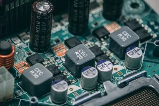
Key components fall into five buckets: power modules (IGBT/MOSFET/SiC), control systems (MCU plus protection relays and contactors), DC power supply auxiliaries, charging connectors and cable assemblies, and the wiring harness [S4]. Capacitors, inductors, current sensors, and signal connectors are matched to the electrical design and validated through thermal and electrical simulation before any PCB is populated.
ABB's high-power modular DCFC cabinets are designed to serve multiple vehicles simultaneously from a shared power stack, a topology that reduces per-port inverter cost but raises grid-interconnect sizing [S2]. Delta's industrial-grade DC fast chargers are positioned for the same heavy-use, high-uptime segment, while Tesla retains vertical integration on connector, cable, and cabinet for the Supercharger line. Buyers evaluating OEM build partners should map connector compatibility, modular scalability, and OCPP firmware support before locking the BOM.
Testing, Compliance, and Failure Modes
End-of-line testing covers three layers: PCB-level in-circuit and functional test, power-module integration test (full-load burn-in at rated current and voltage), and full-system integration including OCPP handshake with a simulated backend [S4]. Compliance testing per UL 2202, UL 2231, IEC 61851-1, and IEC 61851-23 is mandatory for North American and European deployment, and EMC per FCC Part 15 / EN 55011 must be passed before shipment.
The dominant field failure modes are: connector wear and contact resistance drift (mitigated by cycle-rated cables and periodic retightening), DC-link capacitor ageing (mitigated by derated voltage stress and temperature monitoring), and coolant pump seizure in liquid-cooled units above 150 kW. For buyers evaluating supplier reliability, published MTBF figures (commonly 100,000+ hours for the power stack) and service-level agreements on NDT equipment for in-service weld and busbar inspection are the most useful filter, since warranty claims on power electronics dominate total cost of ownership over a 10-year site life.
Trackable signals for the next planning window: IONNA's 1,000-port target by year-end 2026 and the ChargePoint Omni Port rollout, which uses a single connector housing to cover both NACS and CCS vehicles, will determine whether dual-cable cabinet layouts remain standard or get compressed into a single-port form factor for new builds. Procurement teams should also watch SAE J3400 (NACS) standardisation milestones, which continue to reshape connector BOMs across the North American installed base.
See also our earlier report, 2026 Industrial Laser Market: Vendor Map, Cluster Output, and Spec Gates for Buyers.