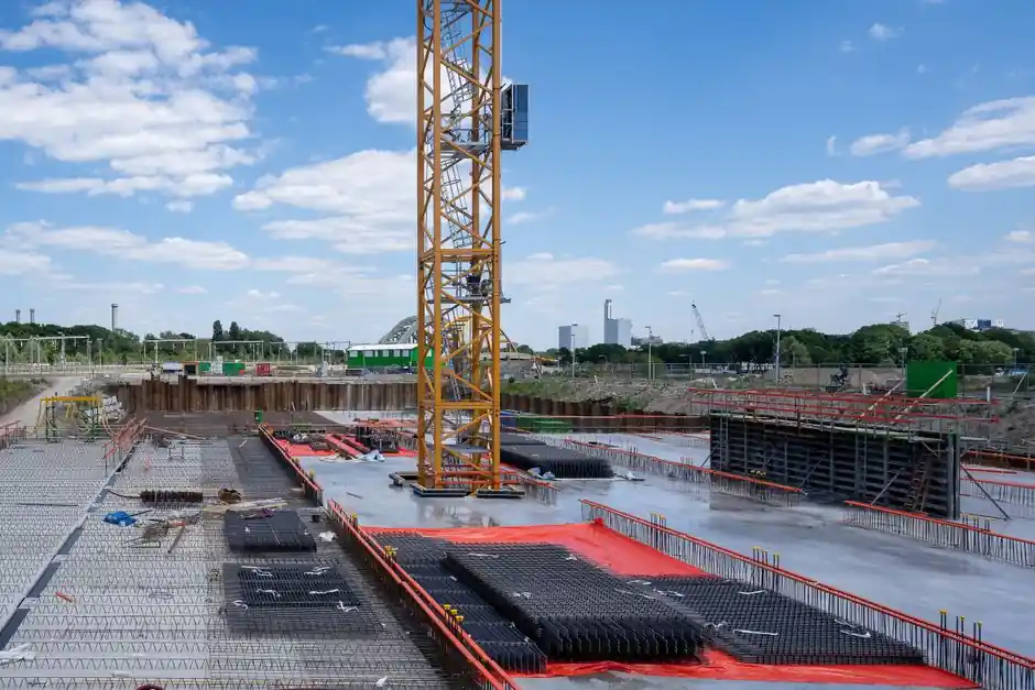
A diaphragm wall grab installation is a six-step sequence built around slurry-supported trenching, with the upper trench stabilized by a pair of lightly reinforced guide walls and the support fluid held at least 2 m above the highest groundwater level at all times [S4].
Wall thickness is selected in discrete steps from 0.5 m up to 1.5 m, trench width is set to 1.0-2.5 times the clamshell width, and individual panel bites run 2.85-3.30 m, giving an assembled primary panel of roughly 6.5-8.0 m before the central merlon bite is removed [S2][S4].
Guide Walls: Geometry, Reinforcement, and Alignment Tolerance
Guide walls are cast in-situ as lightly reinforced concrete elements on both sides of the wall axis, and they are the first permanent reference for every downstream tolerance check [S2]. The guide wall pair has four jobs: outline the structure, guide the grab vertically, store a reserve volume of support slurry, and seat the reinforcement cage before and after concreting [S3].
For diaphragm wall grab installation, the guide walls are typically poured flush against existing structures and foundations, which is the only practical way to build a wall within 100-200 mm of an adjacent property line in tight urban sites [S3]. A pre-excavation step is sometimes needed to remove obstructions before the guide walls are placed, otherwise the grab will refuse to enter the trench on its first bite [S2].
Slurry Circuit: Bentonite Mix, Pump Submersion, and Desanding Targets
The slurry pump must be fully submerged in bentonite before the grab starts the first bite, which is why a small initial excavation is filled with fresh slurry during pre-excavation [S2]. Once circulation starts, the support slurry is monitored for density, sand content, viscosity, and pH at regular intervals, with out-of-spec slurry routed through a desanding plant rather than dumped [S2].
Bentonite is the default thixotropic fluid because it forms a low-permeability filter cake on the trench walls and applies a hydrostatic pressure that counteracts the active earth pressure trying to collapse the panel [S3]. In ground conditions where bentonite is unsuitable, biodegradable polymers can be substituted, but the same density and sand-content limits still apply [S3]. Per NBN EN 1538 the bentonite level must stay at least 2 m above the highest water level across the full trench height, with extra margin where an artesian aquifer is present [S4].
Grab Selection, Panel Geometry, and Excavation Sequence

The choice between a mechanical/hydraulic grab and a Hydrofraise-style cutter is set by soil conditions and trench depth, with grabs preferred in soft to medium soils and cutters required for hard soil or depths beyond grab reach [S3][S5]. Bauer's DHG-V hydraulic grab delivers panel lengths up to 3,800 mm and widths up to 1,500 mm per bite, while record cut depths beyond 250 m have been achieved with the BC cutter range [S5].
The standard excavation order is primary panel first, then secondary panel, then the central merlon bite between them, which keeps the trench stable on three faces while the clamshell is working [S4]. A typical lamella is built in three successive bites: panel 1, panel 2, and the merlon, with the two end bites matched to the 2.85-3.30 m clamshell width [S4]. Soletanche Bachy notes that diaphragm walls can reach 90 m depth and beyond when grab-excavated, with continuous hydrofraise work pushing that envelope much further [S3].
Joints, Reinforcement Cages, and Tremie Concreting
Joint selection is equipment-driven: flat and circular joints are generally avoided, while grooved joints with PVC water stops are preferred in most markets and steel I-beam water stops remain common in the US [S2]. Once the bite reaches depth, removable flat steel joint elements with PVC water stop tapes are installed at both lamella fronts, then the reinforcement cage is lowered and suspended from the guide wall [S4].
The cage must carry enough transverse and diagonal reinforcement to survive the lift without racking, and it has to leave clearance for at least two or three tremie pipes so the concrete can rise uniformly from the base [S2]. Concreting follows the tremie method from the bottom up, with the displaced slurry recovered at the top and routed back through the desanding plant for reuse rather than wasted [S4]. Refer to the broader excavation-handling workflow in excavator installation: quick-hitch plumbing, track fitting, and site setup for the parallel tolerance and acceptance logic applied to the carrier machine sitting on top of the rig.
Platform, Workspace, and Equipment Acceptance Gates
Franki Foundations lists a minimum platform area of 300 m² for bentonite mixing and soil stockpile, with a working width of at least 17 m (15 m from the wall axis plus 2 m in front of the wall) [S4]. The groundwater level must be at least 2 m below the working platform, and the platform itself has to be stable, dry, and flat before any grab work begins [S4].
Vibration-free installation and only engine noise as the acoustic signature are the two environmental acceptance points that matter most on urban sites, alongside controlled disposal of the bentonite slurry and the arisings [S4]. The reference standard for execution in Belgium and many EU projects is NBN EN 1538, which codifies the panel sequence, slurry level rule, and tremie concreting procedure summarized above [S4].
Grab vs Cutter: When to Pick Which Excavation Tool
Pick a diaphragm wall grab when the soil profile is soft to medium, the trench depth is under about 50 m, and panel widths of 0.5-1.5 m match the structural wall thickness you actually need [S4][S5]. Pick a trench cutter when you hit hard or very hard soil, when the depth exceeds grab reach, or when you need a continuous, vibration-controlled excavation in a sensitive urban setting [S5].
For shallow urban projects where the depth is well within grab reach, the hydraulic grab wins on cycle time and capital cost, but it leaves a rougher trench wall than a hydrofraise or BC cutter [S3][S5]. For deep cutoff or structural walls beyond roughly 50-60 m, plan on a cutter from the bid stage because the cut depths above 250 m already proven by Bauer are not achievable with a grab alone [S3][S5]. For the heavy lift side of the spread, compare the carrier options in crawler crane vs overhead bridge crane: selection map for site, capacity, and cycle before locking the crane class into the method statement.
Track two signals over the next quarter: any update to NBN EN 1538 execution clauses, and any new grab tooling release that pushes single-bite width past 1,500 mm or panel length past 3,800 m beyond the current Bauer DHG-V envelope [S5].
Detailed specification references: diaphragm wall grab, linear guide, and crossed roller guide.