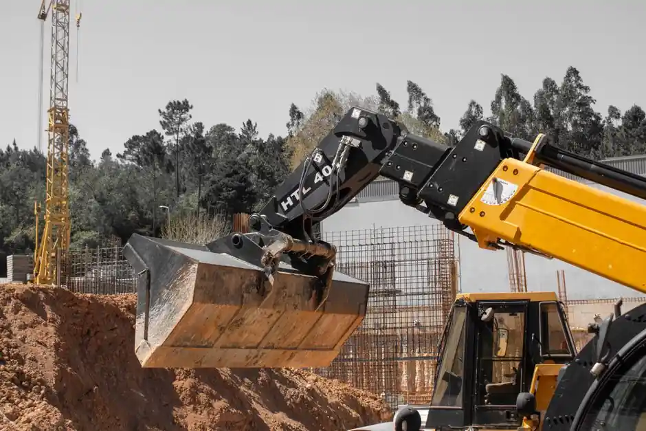
Excavator installation breaks into three field tasks that any 20-tonne-class machine share: weld and route the quick-hitch pilot/solenoid pipeline to the forearm, lay and tension the steel track on level ground, then commission the machine on a firm, flat pad with clear hand-signals between operator and rigger [S1][S2][S3].
Skipping any of those three steps is what kills couplers in the field. A mis-wired solenoid valve, a track that is two links too tight, or a machine parked on a 5° slope is the difference between a productive shift and a hydraulic line blowing off at 210 bar [S1][S3].
Quick-hitch pipeline layout: weld routes, port labels, and the iron-pipe clearance table
Quick-hitch installation starts with welding an iron pipe along the forearm as the rigid spine, then stepping down to flexible hose sections that reach the solenoid valve mounted on the boom base [S1]. The reference build uses five pipe segments (labelled ①-⑤ in the work instruction) joined by 90° butt fittings, with the final segment landing on ports P (pilot oil in) and T (oil return) of a solenoid valve cluster [S1].
The iron-pipe clearance table supplied with the kit is non-negotiable: model 02 sits 150 mm above the forearm, model 04 stays at 150 mm, model 06 climbs to 200 mm, model 08 to 230 mm, and the heavier 10 and 17 classes both require 280 mm of stand-off so the pipe clears the bucket ram arc [S1]. Each 90° joint must be fully seated against the iron pipe before the pedestal is welded, because a 2 mm gap becomes a fatigue crack inside 200 hours of stick-cycle vibration [S1].
Solenoid wiring color code and switch logic: green to valve, red to positive, black to negative
The switch harness uses a fixed three-wire color code: green routes to the solenoid valve coil, red to the positive pole, black to the negative pole, and any swap reverses the actuator logic and can hold the coupler unlocked [S1]. When the cab switch is turned right, the buzzer alarms and the forearm cylinder retracts, pulling the fixed hook over the attachment pin; when turned left, the cylinder extends and the safety pin can be inserted into the identifying hole to lock the coupler per the instruction [S1].
Two hydraulic behaviours matter at install. With the switch OFF, port P still feeds oil to port A whenever the pilot is pressurised, so the cylinder stays topped against the pin in standby, which is exactly the fail-safe condition you want on a working site [S1]. The T port (oil return) must run back to the hydraulic tank or a low-pressure return line, not to a dead-end manifold, or heat will build and the solenoid seals will harden within a season [S1]. For broader context on how quick couplers interact with the host machine, the excavator attachment encyclopedia entry maps the boom-stick-bucket geometry those clearances protect.
Track installation: ground prep, drive-wheel bolt-up, and tensioning
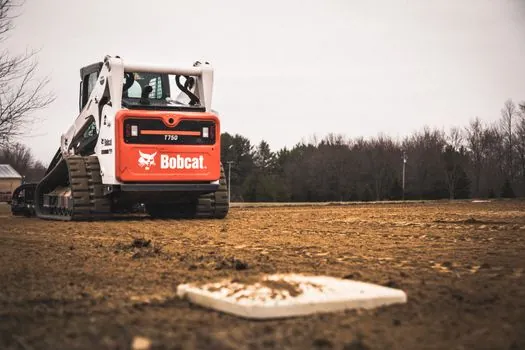
Track installation begins with site prep: a flat, debris-free pad, all bolts and nuts on the new track chain confirmed present, and the excavator positioned with at least one metre of clearance so the assembly can be fed under the undercarriage [S3]. The chain links must be lined up with the sprocket and idler teeth before any bolt is torqued, because a one-tooth offset shears a sprocket boss inside the first 50 hours of travel [S3].
After the track is wrapped around the idler, support rollers, and sprocket, the track pin is seated with a hand hammer, never an air hammer, and the chain is walked forward at idle to check for binding or skipping [S3]. Track tension is the single most-checked parameter post-install: too tight accelerates bushing and sprocket wear, too loose throws the chain off the idler on a side-slope, and a sag of roughly 25-40 mm between the support rollers is the typical field acceptance band on 20-tonne-class machines [S3]. Slow travel in both directions for the first 10 minutes confirms the alignment before any digging load is applied [S3].
Site setup and pre-operation checks: level ground, trained operator, clear communications
Pre-operation begins before the engine starts. The machine must be parked on a firm, level surface, the operator must be able to communicate with ground workers by radio or hand signal, and any bystanders must be cleared from the swing radius and the bucket arc [S2]. The reference operation manual spells out that operators must have completed safe-operation training before any site work, and that all safety signs on the machine must be legible, a frequent audit failure on machines older than five years [S2].
Operators are also responsible for compliance with local regulations on top of the OEM manual, so a US job site will layer OSHA 1926.602 (motor vehicles) on top of the machine's own pre-op checklist [S2].
Installation acceptance criteria: what 'done' looks like on handover

A correctly installed quick-hitch and track assembly meets four measurable checks at handover. First, the solenoid valve responds inside one second of switch actuation, with the buzzer sounding on retract and silence on extend [S1]. Second, the safety pin drops freely into the identifying hole with the cylinder extended, confirming mechanical lock independent of hydraulic pressure [S1]. Third, the track runs without skipping, climbs the sprocket cleanly on both sides, and shows no more than one link of sag between the lower support rollers at rest [S3]. Fourth, no hydraulic fitting on the quick-hitch line shows visible weeping at 210 bar working pressure during a 5-minute hold test [S1].
Failure modes to refuse to ship: any solenoid wire in the wrong colour position, any 90° fitting with a visible gap to the iron pipe, a track tension outside the sag band, or a machine parked on broken ground for handover. For related undercarriage and structural-spec work, the crossed roller guide selection note for agricultural machinery shows how the same tolerance-driven acceptance logic carries across to other heavy-equipment assemblies.
Limits of in-field installation: when to stop and call the dealer
Three conditions mean the install should pause and escalate. Any hydraulic fitting that weeps under the 5-minute hold test must be re-cut, not re-torqued, because cold-cut flare damage does not recover with clamp load [S1]. A track that binds or skips after a correct tensioning pass points to a misaligned sprocket or a stretched chain link, both dealer-floor repairs [S3]. And a quick-hitch cylinder that drifts more than 5 mm in 60 seconds with the switch off has an internal seal failure that the field cannot fix [S1].
Documented handoff: the operator's manual stays in the cab, the solenoid wiring diagram is laminated and clipped to the boom, the track-tension baseline is logged in the maintenance file, and the next 10-hour re-torque is scheduled before the machine is released to production [S2][S3]. For procurement teams sizing a new machine against a power mixer installation scope, the same install-dossier discipline (wiring diagram, torque log, acceptance test) applies across both equipment classes.
Track these signals going forward: revisions to quick-hitch pilot circuit standards (ISO 13031 covers coupler safety), updates to undercarriage tensioning specs on the next OEM service bulletin, and any local regulation changes that add to OSHA 1926.602 or its EU equivalent for excavator commissioning on shared civil sites.
Spec-level background on the components involved: linear guide, and crossed roller guide.