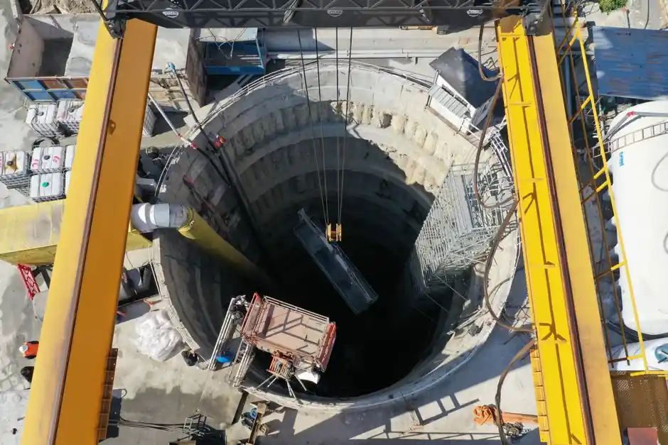
A hydraulic diaphragm wall grab is the workhorse for pipeline corridor shafts, pump-station intakes, and river/utility crossings where watertight excavation support and verticality tolerance of 1 in 150 are required [S1][S2]. Tool choice between grab and trench cutter is governed first by soil strength and trench depth, with grabs dominating in soft to medium-dense soils and trench cutters taking over once rock or very hard strata are encountered [S1][S4].
Standard working envelopes for grabs span 0.6-1.2 m wall thickness and 2.8-3.8 m panel length, with Bauer's DHG V class reaching 3,800 mm panel length and 1,500 mm trench width, while cutter rigs such as the BC family have logged depths above 250 m [S1][S5]. Pipeline contractors typically sit in the grab envelope: pump-station shafts and trenchless launch/receive pits rarely exceed 40-50 m and the alignment is usually over soft alluvium or weathered rock, not competent basement [S2][S4].
Grab vs Cutter: The Depth-and-Soil Cutover
Specifying engineers should treat the grab/cutter decision as a function of two variables: SPT N-value (or equivalent rock strength) and design trench depth, per the standard construction sequence where a trench grab or cutter loosens the soil under bentonite or polymer support fluid [S4]. Rope-operated 2.8 m grabs are widely used to dig into soil and very weak rock, but become slow and vibration-prone when chiselling is required, which is where hydraulic grabs and hydrofraise cutters take over [S5].
Vertically, the cutover is sharp: rope grabs align to the 1 in 100 piling tolerance baseline, while hydraulic grabs with integral monitoring instrumentation meet the 1 in 150 verticality deviation recommended in the ICE Specification for piling and embedded retaining walls (Institution of Civil Engineers 2017) [S5]. Hydrofraise reverse-circulation cutters remove the depth sensitivity of spoil handling, lifting excavation rate off depth once the rock can be milled into suspension [S5]. Bauer BC cutters have surpassed 250 m trench depth in the field, a benchmark the grab family does not approach [S1].
Panel Geometry and Joint Strategy for Pipeline Shafts
Panel geometry is set by grab width and minimum bite length, not by structural demand alone: minimum panel length is governed by grab size and typically starts at about 3.0 m, while multi-bite primary panels reach 6.5-8.0 m in stable soils [S2]. Standard diaphragm wall thickness sits in a 0.6-1.2 m band, with panels cut in 2.8 m or 6.0-7.0 m lengths and joined by inter-panel joints [S5].
Joint type is partly an equipment decision: flat panels and circular joints are generally avoided, grooved joints with water stops are the typical preference, and steel I-beam water stops remain common in US practice [S2]. For pipeline work, the joint choice has to balance hydrostatic head (often 10-30 m of groundwater at river crossings) against the verticality the grab can hold across full panel depth. Guide walls are non-negotiable: they set horizontal alignment, confine the upper trench, and guide the grab vertically during the first critical meter where the trench is least stable [S2][S4][S5].
Slurry Circuit, Desanding, and Tremie-Concrete Discipline
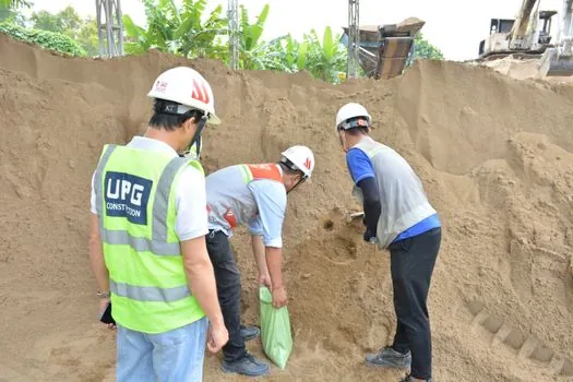
Slurry management is where pipeline-shaft diaphragm walls fail or succeed, irrespective of grab choice. Before the grab starts, the pump must be fully submerged in bentonite slurry; an initial grab pass then fills with slurry to stabilise the trench, with pre-excavation used to clear obstructions above guide-wall level [S2]. During excavation, slurry is circulated through the desanding plant at regular intervals and density, sand content, viscosity, and pH are kept inside acceptable limits; fresh slurry is a fallback, not a default, because it is uneconomical [S2][S4].
For tremie concreting, the cage must leave room for at least two or three tremie pipes so placement can proceed from the bottom up while displacing slurry, with the recovered slurry routed back through the desander [S2]. In pipeline work, this step usually gates the critical path: tremie head, embedment depth, and the slurry/groundwater head differential are the three parameters that determine whether the wall comes out watertight [S4]. Related pipeline-corridor work such as pile driver selection for trenchless pipeline construction follows the same soil-and-tool logic, and the broader equipment-class view is laid out in the construction machinery and equipment map.
Spec Map: Matching Grab Class to Pipeline-Shaft Conditions
For typical pipeline shaft and intake construction, the selection map lines up as follows, with the grab class as the row header and depth, soil, and panel length as the decision columns. [S2]
1) Rope-suspended 2.8 m grab: trench depths to roughly 30-40 m, SPT N below ~20-30 (soft to medium-dense clay, silt, sand), panel length fixed at 2.8 m, verticality 1 in 100, lowest mobilisation cost [S1][S5]. 2) Hydraulic diaphragm wall grab (e.g. DHG class): depths to about 50-60 m, SPT N up to ~30-40, panel length 2.8-3.8 m and width up to 1,500 mm, verticality 1 in 150 with instrumentation [S1][S5]. 3) Hydraulic grab with chisel assist: same envelope as the hydraulic grab but extended into weak rock; productivity drops and vibration becomes a neighbour-relations issue in urban pipeline work [S5]. 4) Hydrofraise/cutter: only when depth exceeds ~60 m, SPT N is well above 40, or rock is present; spoil is pumped as slurry rather than lifted by grab [S1][S5].
Pipeline work almost always lands in rows 1-3. The diaphragm wall grab reference entry on the construction-tools side collects the same panel and depth envelopes, while the pipeline pump station page shows the upstream hydraulic demand the shaft is being built to serve.
Who the Grab Is (and Is Not) For
Hydraulic and rope grabs are the right tool for pipeline construction's bread-and-butter shafts: pump-station forebays, valve chambers, jacking/receiving pits for microtunnelling, and river or highway crossing cut-offs where the wall acts as both retention and groundwater barrier [S3][S4]. They are a poor fit for very deep (>60 m) secant-pile alternative walls, for rock sites where the cutter wheel is the only realistic excavator, and for very tight urban plots where the larger hydrofraise plant and slurry circuit cannot be mobilised [S1][S5].
Market context supports the grab-heavy mix: the global diaphragm wall grab segment was valued at $0.99 billion in 2026 and is forecast to reach $1.72 billion by 2035, a 6.33% CAGR, driven by urban infrastructure, water and sewer tunnel programmes, and metro/transportation expansion [S6]. Pipeline corridor work sits inside that demand pool, alongside shaft work for pile driving equipment and trenchless pipeline tools such as the diaphragm pump slurry-handling circuit.
Quality Control: Verticality, Slurry, and Joint Watertightness
Three measurable criteria govern acceptance on a pipeline-shaft diaphragm wall: verticality and position tolerance, joint and concrete watertightness, and reliable structural continuity at connections [S4]. Verticality is verified with inclinometers and calipers across full panel depth; the 1 in 150 hydraulic-grab target is the published benchmark, against 1 in 100 for rope grabs [S5]. Slurry properties (density, viscosity, sand content, pH) are logged at regular intervals through the desanding cycle rather than only at the end of excavation [S2][S4].
Joint detailing deserves the same QA weight as the concrete itself: stop-end profiles, water bars, and sealing strips are selected with both the excavating equipment and the contractor's panel-sequence preference in mind, and grooved joints with water stops dominate current best practice outside the US steel I-beam convention [S2]. For pipeline work, where the wall is a permanent groundwater cut-off as much as a temporary retention system, a failed joint is a 30-year maintenance liability, not a punch-list item.
Trackable Signals for the Next Planning Cycle

Two signals are worth watching on a 6-12 month horizon: (1) further hydrofraise deployments in soft-ground urban projects, following the New Zealand first-use case, which would push the depth/rock cutover deeper into traditional grab territory [S5]; (2) the 6.33% CAGR trajectory of the diaphragm wall grab market through 2035, which is the clearest quantitative read on whether utility-tunnel and water/sewer pipeline programmes are continuing to absorb grab-class capacity at the 2026 baseline of $0.99 billion [S6].