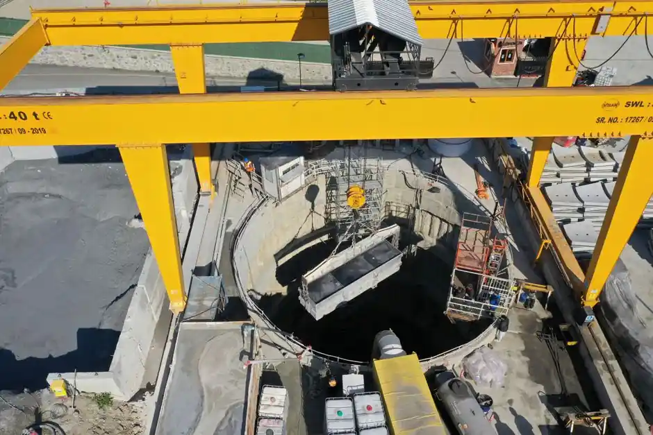
A tunneling-grade diaphragm wall grab is selected by matching machine class to panel depth, soil class, and joint detail, not by excavator size alone. Working depths cluster at 20-50 m for hydraulic trench grabs and extend to 80 m when a diaphragm wall cutter is used in rock or mixed-face conditions [S5].
For metro stations, cut-and-cover tunnels, and shaft access, panel length is governed by grab bite width, with single-bite panels starting near 3.0 m and multi-bite panels reaching 6.5-8.0 m, depending on whether primary panels are subdivided left-right-middle [S1]. The selection matrix below reflects published guidance for tunneling-adjacent work.
Selection Drivers: Depth, Soil, and Panel Geometry
Diaphragm wall cutoffs for tunneling projects are typically specified in the 20-80 m depth band, with slurry trench walls limited to 10-50 m in soft to medium soils [S5]. The minimum practical panel length is set by the grab footprint, generally around 3.0 m, and T-panels or corner panels require multi-bite sequences to reach 6.5-8.0 m [S1].
Soil class dictates the grab class. Cohesive fills and medium-dense sands stay within standard cable-hydraulic grab capability; mixed-face profiles with boulders or weathered rock push the specification toward a diaphragm wall cutter or a chisel-assisted hydraulic grab. Pre-excavation to remove surface obstructions is a documented step before the slurry pump is fully submerged in bentonite, and the first bite is sized so the trench fills with slurry before vertical digging starts [S1].
Guide wall geometry controls tolerance. Guide walls are lightly reinforced concrete elements set above grade to maintain horizontal alignment, confine the upper 1 m of trench, and act as the reaction frame for the grab; they are non-negotiable for tunneling projects where settlement of adjacent utilities must stay below 10-15 mm [S1][S3].
Grab Types Compared for Tunneling Reach
Three grab configurations dominate tunneling specifications: single-clamp mechanical/hydraulic grabs for shallow standard panels, heavy hydraulic grabs for deeper urban metro shafts, and cutter rigs for depths beyond 50 m or where rock exceeds standard grab penetration [S2][S5]. Single-clamp grabs suit standard trench widths in stable ground and remain the lowest-risk rental option for foundation projects and retaining walls in soft soils [S2].
For deep metro stations where panels must reach 40-60 m through sandy gravels or stiff clays, a hydraulic grab with kelly-bar extension is the typical choice, paired with real-time verticality monitoring via inclinometer in the grab body. Where tunneling interfaces with rock-head profiles, a diaphragm wall cutter replaces the grab for the rock portion, since the cutter mills through rock that would stall a conventional grab.
Slurry management is the binding constraint across all three classes. Trench walls must remain stabilized by bentonite or polymer slurry with controlled density, viscosity, sand content, and pH throughout excavation, and the slurry head must stay above the groundwater table by a defined differential to keep the filter cake intact [S1][S3]. The cut-off wall function ties directly to a maximum hydraulic conductivity specification of 1 x 10^-7 cm/sec for soil-bentonite slurry trench cutoffs, a benchmark often referenced for tunneling cutoff designs [S5].
Joint Design and Water-Tightness for Tunnel Walls
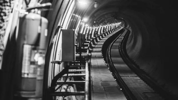
Joint selection for tunneling diaphragm walls balances constructability against water-stop performance. Available joint geometries include flat, circular, steel I-beam, and grooved joints with water stops; grooved water-stop joints are generally preferred, while in the US steel I-beam water stops remain common [S1]. Flat and circular joints are typically avoided for permanent cut-and-cover tunnel walls because they offer limited water-stop continuity at the interface [S1].
The joint detail interacts with the grab bite sequence. Because primary panels are excavated first and secondary panels close against them, the joint profile of the primary panel must be cut cleanly by the grab, which means grab bucket width and side-wall cutting geometry are not optional specifications for tunneling work. For projects near rail corridors or active utilities, the joint is also the deformation control plane, and any overcut or verticality drift at the joint propagates into measurable lateral wall movement during subsequent excavation.
Reinforcement detailing at the joint must leave space for at least two, and typically three, tremie pipes so concrete can rise from the bottom without entraining slurry, a placement that defines the watertightness of the finished panel [S1][S3].
Slurry, Tremie, and Tolerance Discipline
Slurry cleaning and desanding is a continuous, not terminal, operation. Density, sand content, viscosity, and pH are tracked while the panel is being excavated, and slurry is circulated through a regeneration plant at regular intervals; fresh-slurry-only operations are technically possible but rarely specified because of cost and waste handling [S1]. Loss of filter-cake integrity is the most common root cause of trench collapse and post-excavation seepage at tunnel walls.
Concreting by tremie method requires the tremie pipe to remain embedded in fresh concrete throughout placement, with the pipe lifted progressively as the concrete head rises; the support fluid is displaced upward and recovered for regeneration [S3]. Execution tolerances tracked in tunneling work include verticality, panel length, panel thickness, and concrete cover, with inclinometers and caliper logs providing the audit trail for sign-off against specification [S3].
Wall head trimming and connection to bracing or slabs is the final interface, executed after pit excavation, using low-vibration demolition tools to expose reinforcement cleanly without damaging the structural concrete below the cut-off elevation [S3].
Where Grabs Fit, and Where They Do Not
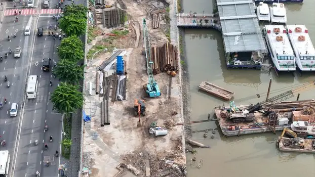
Diaphragm wall grabs are the right tool for tunneling projects where depth is 20-60 m, soil is granular to medium-stiff cohesive, and panel length is 3-8 m, with a tolerance budget in the tens of millimeters and a permeability target at or below 1 x 10^-7 cm/sec at the joint [S1][S5]. They are not the right tool for hard rock tunnels, where a diaphragm wall cutter or raise-bore methods replace grab excavation entirely.
For procurement teams evaluating fleet decisions across adjacent civil works, the same selection logic that drives grab vs. cutter choice in tunneling also drives equipment decisions in trenching and quarry work, where the quarry trenching grab spec map walks the same hydraulic-vs-mechanical tradeoff at shallower depths. For owners standardizing procurement across multiple sites, the machine tool procurement strategy for 2026 framework applies the same spec-matched discipline to underground-works fleet planning.
Two trackable signals to watch over the next planning cycle: (1) rental availability of cutter rigs for the 60-80 m band, which remains the tightest supply segment for tunneling diaphragm wall packages, and (2) slurry regeneration plant capacity at urban metro sites, where space constraints are pushing more contractors to polymer slurry in place of bentonite, with corresponding shifts in the desanding and disposal workflow [S2][S5].
Component reference pages worth checking: diaphragm pump, and diaphragm valve.