A 145 t carrier machine fitted with a 25 t grapnel, such as the SH950 H11 diaphragm wall grab, can drive into strongly weathered rock strata up to 10 MPa unconfined compressive strength, with bucket open-close cycles around 9 seconds [S1]. These grabs are the heavy end of the diaphragm wall grab family and overlap with quarrying where soft to medium rock has to be removed in panel form before wall pouring.
Quarrying-class panels built with a hydraulic grab method typically reach 10.5-30 ft (about 3.2-9.1 m) per panel, with standard thicknesses of 32, 36, 42, 48 and 60 inches (about 800-1,500 mm) and wall depths commonly above 50 m [S2]. The DHG V configuration delivers trench widths up to 1,500 mm and panel lengths up to 3,800 mm, with cylinder forces of 1,200 kN or 1,800 kN depending on soil target [S3][S4].
Carriers, engine power and machine envelope
Grab carriers in the BAUER GB series scale from 15 t-class compact low-headroom units to 32 t mainline rigs, with the GB 50 specified at 280-310 kW engine output and approximately 17.3 m overall height, while the GB 80 S runs a 310 kW engine at roughly 18.5 m height and is rated to 80 m trench depth [S1][S4]. The DHG-LT low-headroom grab is engineered for sites with constrained working height, paired with a 15,000-22,000 kg carrier, a 2,800 mm trench length envelope, an 800-1,500 mm trench width band, and a 2 x 450 kN cylinder force [S1][S4].
For quarrying crossover projects, the practical selection gate is the carrier mass divided by trench depth: heavy 145 t units with 25 t grapnels target strongly weathered rock to 10 MPa, while mid-range 32 t carriers on 280-310 kW engines are reserved for soil-class panels to 50-80 m depth [S1][S4]. Power density in the 9-10 kW/t carrier band is typical for this segment.
Grab geometry, panel dimensions and rock impact capability
Diaphragm wall grabs cut rectangular panels rather than round holes, which is why the geometry window is unusually tight: 2,400-3,800 mm trench length, 600-1,500 mm trench width, and grapnel mass in the 15-25 t band [S3][S4]. The 9-second open/close cycle on high-impact units such as the SH950 H11 sets the productivity cadence, since each cycle is one grab pass through the slurry-stabilised trench [S1].
Standard wall thickness bands of 32, 36, 42, 48 and 60 inches (about 800, 900, 1,050, 1,200 and 1,500 mm) line up with the 600-1,500 mm width window the major hydraulic grabs can produce, so panel thickness and grab width are coupled, not independent choices [S2][S4]. Where the host material crosses 10 MPa UCS, the practical rule is to switch from grab excavation to a trench cutter, because cutter BC units have reached depths beyond 250 m in hard soil and rock conditions [S3].
Comparison: grab, cutter, and drill-side alternatives
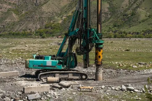
The decision between a grab, a cutter, or a grab-auger hybrid comes down to four criteria: ground hardness, trench depth, panel geometry, and noise or headroom limits [S3]. A grab suits soft to medium soil and weathered rock, with 600-1,500 mm widths and 2,400-3,800 mm panel lengths, typically cycling in single-digit seconds, and is the only option that can be packaged into a low-headroom 15,000-22,000 kg carrier for confined urban shafts [S1][S4]. A trench cutter takes over in hard or very hard soil and at large trench depths, with no interruption of excavation during slurry desanding, and recorded depths above 250 m on the BC cutter line [S3].
A grab-auger rig, where the diaphragm wall drilling tool is lowered and rotated to loosen soil or weak rock before the grab cleans the trench, is a middle path suited to mixed-face quarrying conditions where harder bands interrupt softer matrix [S7]. For typical diaphragm wall practice the trench is stabilised with bentonite or polymer slurry throughout excavation, and panels are poured by tremie pipe after cage and joint installation, so grab-versus-cutter choice does not change the downstream concreting sequence [S5].
Verticality control and instrumented grabs
Hydraulic grabs such as the MODELCO CHA are fully instrumented, with real-time verticality monitoring and correction in two or three axes during excavation, which is a hard requirement where wall tolerances and adjacent structures are tight [S1]. A stable filter cake on the trench walls plus controlled slurry density, viscosity, and sand content are the process enablers that keep verticality deviations inside the spec window until tremie concreting closes the panel [S5].
Lower-cost grabs such as the CMS target medium 40-60 t carrier cranes with 12-16 t winch line pull, which sets a minimum rigging floor for any quarrying deployment that uses a generic crawler crane rather than a purpose-built grab carrier [S1]. The CH8 hydraulic grab is designed to mount on a standard excavator, with 360 deg swing rotation and high jaw closing force, accepting the lower impact energy of an excavator base in exchange for transport simplicity on remote quarry sites [S1].
Quarrying crossover: where grabs make sense, and where they do not
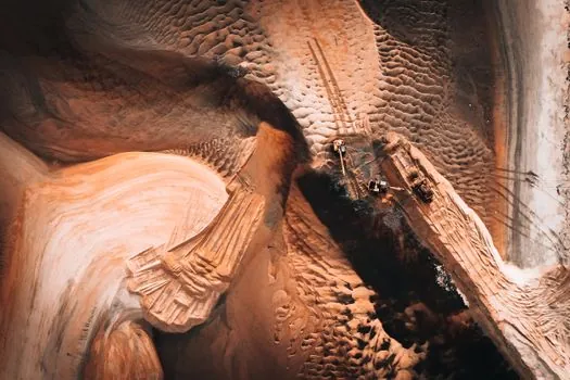
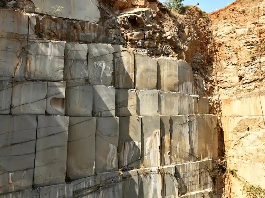
Grabs are appropriate on quarrying and quarry-adjacent projects where the cut is essentially a deep, narrow, rectangular slot in soft to medium rock, where slurry trench support is acceptable, and where the panel layout can follow the 600-1,500 mm thickness ladder without exotic geometry [S2][S3]. They are not appropriate where the rock mass exceeds roughly 10 MPa UCS across the full depth, where panel length must break the 3,800 mm envelope, or where vibration, noise, or headroom rules out a heavy impact cycle [S1][S3].
For deeper or harder rock the right call is to keep the diaphragm wall methodology but switch the tool to a BC-class trench cutter, since cutter units have set depth records past 250 m and run continuous excavation during slurry desanding [S3]. Where the ground is mixed-face soft soil with hard bands, a grab-auger rig is the compromise that lets the grab clean out the loosened material between auger passes, and the rig can be reconfigured from the same base carrier used for soil-only panels [S7]. Buyers comparing this equipment category against other heavy plant should weigh the 9-10 kW/t carrier power density, 15-25 t grapnel mass, and 1,200-1,800 kN cylinder force as the three numbers that actually decide whether a given machine will break ground in a quarrying context [S1][S4].
Trackable signals to watch next: any new grab carrier announcements in the 30-50 t class with engine output above the current 310 kW ceiling on the GB 80 S, and any extension of the DHG-V trench length past 3,800 mm for deeper quarrying-style panels, since both would shift the grab-versus-cutter crossover point in the specification chain.
Component reference pages worth checking: diaphragm pump, and diaphragm valve.
Background reading: Safety helmet sizing: head circumference, shell-shape fit, and a buyer's shortlist.