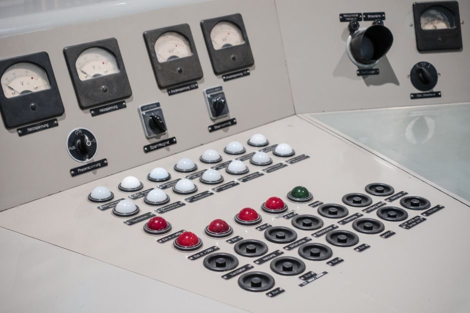
A digital panel meter is specified by the loop it sits on, not by the cut-out in the cabinet door: input signal type (DC V/DC mA/AC V/RTD/TC/frequency/process), full-scale range, display digit count, accuracy class, supply power and I/O dictate whether the instrument reads a 4-20 mA loop, a Type K thermocouple, a 0-10 V setpoint or a 50/60 Hz tachometer pulse train correctly.
Selection mistakes almost always originate from one of four gaps: the meter accepts the wrong signal class, the meter's supply voltage conflicts with loop power (the classic 2-wire versus 4-wire confusion), the display count resolution is too coarse for the process band, or the meter's accuracy class is not stated at the same reference (F.S. versus rdg) as the rest of the loop.
Input Signal Class and the 2-Wire vs 4-Wire Question
2-wire (loop-powered) digital panel meters draw their operating current from the same pair of wires that carry the 4-20 mA process signal, so they appear in series with the transmitter and need only a signal pair plus a shunt [S5]. A 4-wire (AC/DC-powered) DPM has separate power and signal terminals; the signal input is a passive measurement and the meter's supply is independent of the loop (typical supplies are 85-265 VAC or 24 VDC, as listed on the YOTO DU series data sheet) [S2]. Specifying a 2-wire meter on a 4-wire loop leaves the operator with a dead display until the loop is re-wired; specifying a 4-wire meter where the field only has 2 wires forces an extra power tap.
Process inputs span DC voltage, DC current (with internal shunt), AC voltage, AC current, RTD (Pt100/Pt1000), thermocouple (J/K/T/E/R/S/B with cold-junction compensation), frequency/RPM, and process inputs scaled to engineering units. A DU-series meter showing 0-9999 counts with 4-20 mA analogue output is the canonical DC current input case [S2]. Confirm the meter's minimum input span: a meter rated 0-500 V AC will not resolve a 0-50 V signal, and a 0-50 V unit will give erratic readings above 50 V even though the digits are still lit.
Display Resolution, Digit Count and Readability
Digit count defines the raw resolution: a 3.5-digit meter reads 0-1999 counts, a 4.0-digit meter reads 0-9999 counts, and a 4.5-digit meter reads 0-19999 counts [S2]. A 4-20 mA process signal mapped across 1999 counts gives roughly 8 μA per count; mapped across 19999 counts it is 0.8 μA per count, which is the practical limit for a 24-bit ADC front end. For an operator watching a tank level between 30% and 70%, the 4-digit 0-9999 count format (e.g. DU series with 8-inch-wide 4-digit LCD) gives plenty of headroom and stays within common shunt tolerances [S2].
Readability depends on three things: digit height (0.3" / 0.56" / 1.0"+), display technology (LED for high-blight outdoor panels, LCD for low-power cabinet doors), and color (red is the default industrial choice, green is used where red might be misread as an alarm). A low-power red LED meter is dimmer than a standard-intensity LED meter of the same digit height; plan for a higher-intensity module or a backlit LCD when the panel sits in direct sunlight [S5]. A 14 mm (0.56") red LED is the typical shop-floor compromise; 25 mm (1.0") and above is reserved for 10+ meter read distances.
Accuracy Class, Reference Conditions and Hysteresis

Accuracy is always quoted with a reference: "±0.2% of F.S. ±1 digit" means the error is 0.2% of the full-scale reading plus one count of the display, while "±0.1% of rdg ±2 digits" anchors the error to the actual measured value. Industrial 4-20 mA DPMs commonly sit in the 0.1% to 0.5% F.S. band; the YOTO DU series is published at 0.2% F.S. with adjustable hysteresis for stable indication on noisy loops [S2]. When the loop is hotter than 23 °C ±5 °C, add the temperature coefficient (typically 0.01% F.S./°C for mid-range meters) before comparing two vendors' accuracy claims.
Hysteresis is the deadband the meter applies between rising and falling readings: without it, a noisy 4-20 mA signal will jitter the last digit and alarm operators; with it, the display is steady and the trip output does not chatter. The DU series exposes hysteresis as a key-programmable setting, which is the reason a hysteresis-enabled meter is preferred over a raw panel meter for any signal sourced from a transmitter with > 0.5% ripple [S2]. For RTD or thermocouple inputs, the comparable parameter is reference-junction accuracy (CJC error is typically ±1 °C to ±2 °C for a T/C DPM) and lead-wire compensation (2-wire / 3-wire / 4-wire RTD configurations).
Power Supply, Isolation and Loop Loading
Supply options cluster into three groups: 2-wire loop-powered (3.5-35 VDC across the 4-20 mA pair, 3.6 mA or 4 mA typical burden), 24 VDC powered (separate terminals, 4-wire meter with active signal input), and universal AC/DC (85-265 VAC or 100-300 VDC). Loop voltage drop is the binding constraint for 2-wire meters: a loop-powered DPM with a 4 V drop, sitting between a 24 VDC power supply and a transmitter that needs 12 V minimum, leaves only 8 V headroom for the wire run, which is fine on a 50 m cable and marginal on a 200 m cable. [S1]
Galvanic isolation between input, power and output is a paid-for feature on most industrial DPMs and is mandatory where the signal ground and the supply ground are at different potentials (long cable runs, separate MCCs). 1500 VAC or 2500 VAC hipot is the typical isolation rating; the output side carries the analog retransmission (isolated 4-20 mA proportional to displayed value) and the discrete outputs (relays rated 5 A at 250 VAC, or open-collector NPN/PNP transistors rated 100 mA at 30 VDC). Confirm the relay contact rating against the actual coil inrush — inductive loads (solenoids, contactors) need a derating of 30-50% on resistive ratings.
I/O Options: Relays, Analog Output and Serial Communications
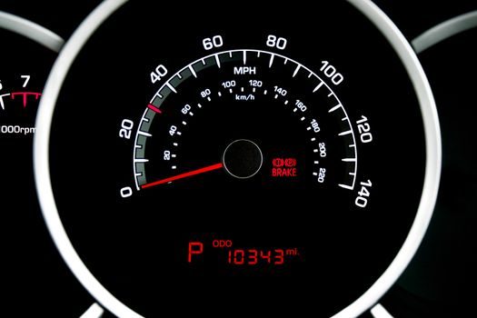
The base DPM reads and displays; the I/O options turn the meter into a control element. Relay outputs (typically 2 SPDT, 5 A at 250 VAC) drive alarms, trips or start/stop commands; analog 4-20 mA retransmission mirrors the displayed value into a PLC or chart recorder; RS-485 with Modbus RTU (or the less common RS-232) is the standard serial option for SCADA and HMI panel integration [S2]. The YOTO DU series lists both an analog 4-20 mA retransmission and an RS-485 interface as configurable options on the same meter [S2].
Selection by I/O looks like this: a single alarm (e.g. high-level cutoff) needs one relay; two independent setpoints need two SPDT relays; a SCADA-trended loop needs Modbus RTU; a stand-alone chart recorder needs isolated 4-20 mA. Expansion modules from AutomationDirect add analog output, discrete outputs or serial communication as sidecar cards on the same panel cut-out, so a meter bought today can grow into a controller tomorrow without re-cutting the panel [S4]. Avoid the trap of using a digital multimeter where a DPM is required — a DMM is a handheld diagnostic tool, not a panel-mount instrument, and its input impedance and isolation are not designed for permanent 24/7 in-loop operation.
Comparison Table: DPM Options Against Four Selection Criteria
The four most common DPM configurations in industrial cabinets, lined up against signal class, accuracy, supply and I/O: [S2]
<strong>2-wire loop-powered (3.5-digit, 0.1% F.S.):</strong> Signal = 4-20 mA only; Accuracy ~0.1% F.S. with 1-2 digit jitter; Supply = drawn from loop; I/O = display only or one alarm. Best for remote tanks where running extra wires is uneconomic.
<strong>4-wire 24 VDC process meter (4-digit, 0.2% F.S.):</strong> Signal = DC V, DC mA, RTD, TC, frequency; Accuracy 0.2% F.S. with hysteresis [S2]; Supply = 24 VDC; I/O = 2 relays + 4-20 mA + RS-485 (e.g. DU series) [S2]. The default workhorse for OEM cabinets.
<strong>4-wire universal AC panel meter (4.5-digit, 0.05% F.S.):</strong> Signal = DC V, DC mA, AC V, AC mA, RTD, TC, process; Accuracy 0.05% F.S. plus CJC ±1 °C; Supply = 85-265 VAC; I/O = 2-4 relays + 4-20 mA + Modbus. Used in switchgear panels and test benches.
<strong>Multi-channel scanner DPM (8-32 channels, 0.1% F.S.):</strong> Signal = mixed (V, mA, TC, RTD); Accuracy 0.1% F.S.; Supply = 24 VDC or 85-265 VAC; I/O = Modbus TCP / RS-485 + 4-20 mA. Used where a single ALC panel or PLC rack needs to monitor many field points without dedicating a DPM per point.
Use Cases, Failure Modes and Sourcing Signals
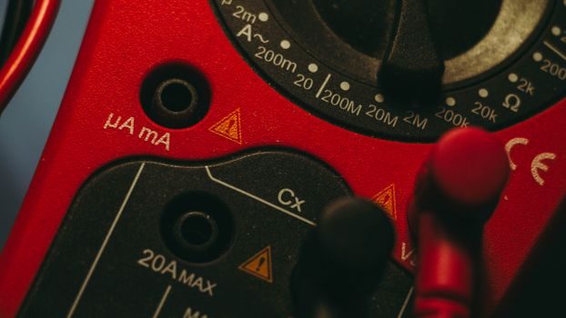
Three field patterns drive most DPM purchases. First, retrofit of an old analog panel meter where the operator now wants a precise 4-20 mA retransmission into a SCADA system: a 4-wire 24 VDC meter with two relays and an analog output is the typical bill of materials, and the existing 72 x 72 mm or 96 x 96 mm DIN cut-out is reused. Second, OEM skid build (compressor, chiller, pumping skid) where 8-16 meters ship pre-wired to a common bus: a 4-wire universal AC meter with Modbus RTU collapses the wiring to a single RS-485 trunk and a 24 VDC auxiliary rail. Third, hazardous-area panel where an explosion-proof enclosure forces a window-mount meter: a 4-wire loop isolator sits inside, the DPM sits on the window, and a 4-20 mA signal is brought out via a certified barrier — matching the patterns used in process-control retrofits covered in the PID controller buying guide for 2026. [S3]
Failure modes to plan for: a 2-wire meter powered from a loop that has been shorted to ground at the field end will read zero, not an over-range; a 4-wire meter's analog output will saturate at the programmed upper scale (e.g. 20.000 mA) regardless of the input, so a wiring error in the field shows as a flat-line reading, not a hard fault. Always specify the meter's over-range and under-range behavior (display flashes, shows "----" or reads -1999) before buying, and confirm the relay state on power-up (fail-safe normally open vs normally closed) — these two details are where most commissioning delays are spent. Final sourcing check: confirm the manufacturer's published mean time between failures (MTBF) and the panel cut-out drawing match the cabinet's metalwork, and verify the meter ships with the correct gasket if the panel is rated NEMA 4 / IP65 front face.