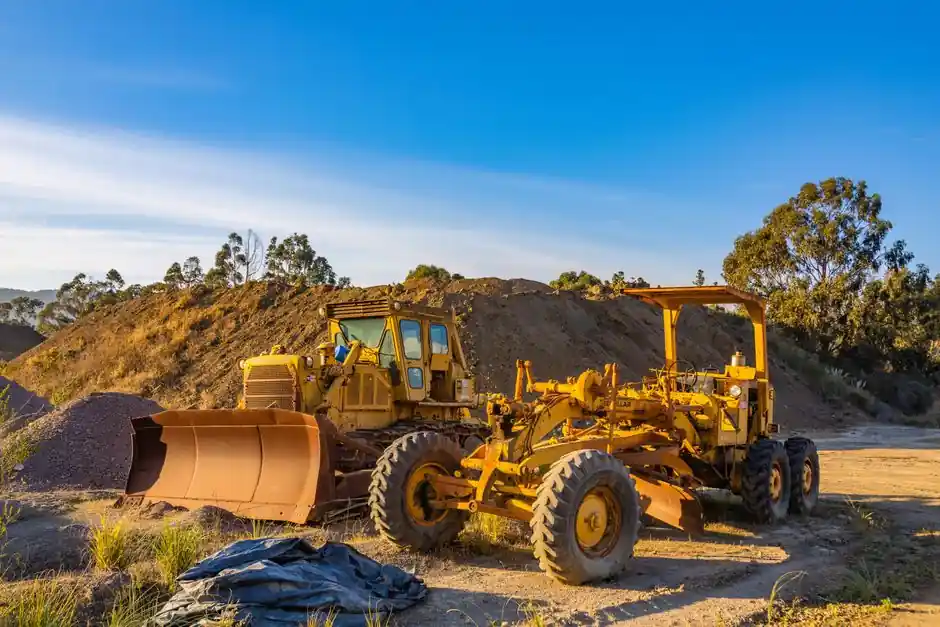
Dynamic compaction densifies natural and fill deposits to depths of 10 to 35 ft below grade, far below the 50 to 200 mm zone reached by a standard steel-drum, sheep's-foot, or grid roller [S1][S3]. The method relies on repeatedly dropping a heavy weight from a crawler crane, transferring up to 25 kJ of impact energy per blow into the in-situ soil and producing a depth of influence of 2 m or more per pass [S3].
For highway and rural road work, dynamic compaction is specified when the subgrade would otherwise require excavation, hauling, and replacement of weak or high-clay soils, with documented cost savings of up to 60% on the cut-to-fill, crushing, and screening chain [S3]. The method is also used in pipeline corridors, where the German DGMK research project (2018–2024) found that dynamic measures are practically the norm for reaching required bearing capacity under roads [S4].
Soil Class as the Primary Selection Driver
Soil type is the primary factor in determining which compactor class fits a given roadbuilding job, and dynamic compaction maps to a specific subset of that soil matrix [S2]. The method handles granular fills, sandy soils, and high-clay "cotton" soils that would normally be excavated and wasted, by shearing particles in place and pushing density high enough to block water ingress into the subgrade [S3]. For shallow granular layers, a conventional road roller still wins on cycle time; for deep or variable fills, dynamic compaction enters the spec at the tender stage.
Where weak saturated clays or organic layers dominate, dynamic compaction must be paired with a wick-drain or pre-loading program, and the depth of influence must be re-derived from a trial grid rather than read off a brochure. Soil Solutions documents that challenging cotton soils with high clay content can be remediated in place, removing the borrow-pit haul that typically drives 30 to 50% of small-road budgets [S3]. The same energy budget that breaks down clay structure can liquefy a saturated silt, so a CPTU probe ahead of mobilization is non-negotiable.
Depth of Influence and Energy per Blow
The classic design window for dynamic compaction on highways is a 10 to 35 ft (roughly 3 to 10.7 m) densified depth below grade, achieved by selecting tamper weight and drop height to match the target layer [S1]. A typical high-energy impact compactor delivers up to 25 kJ per blow, with a 2 m plus depth of influence per pass, against the 50 to 200 mm influence of a drum or padfoot roller on the same pass count [S3]. This is the single biggest reason dynamic compaction enters the bill of quantities for mine haul roads, airport runways, and rail layer works rather than urban street overlays.
Energy per blow is set by tamper mass (commonly 5 to 25 t) and drop height (10 to 30 m), then verified with a trial drop grid before production. A standard rule of thumb in the 1986 USDOT guideline is that the depth of significant densification is roughly proportional to the square root of the drop energy, with 10 ft achieved by light tampers and 35 ft requiring the heaviest weights in the fleet [S1]. The same guideline ties applied energy to the resulting bearing capacity, with 100 to 150 kPa (roughly 2,000 to 3,000 psf) commonly enough to carry conventional spread footings after treatment [S5].
Selection Criteria: Dynamic Compactor vs Standard Roller Train
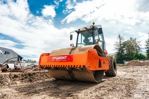
Three criteria separate a dynamic compactor from a construction machinery and equipment roller train on a road job: depth of influence, soil class tolerance, and unit cost per cubic meter densified. The dynamic compactor wins on depth (2 m plus versus 0.2 m) and on weak or high-clay soils that defeat vibratory drums, with savings up to 60% reported on the cut-to-fill, crushing, and screening chain [S3]. The standard roller train wins on cycle time, finish tolerance, and capital cost for shallow lifts under 300 mm.
For a 1 km rural road over 4 m of variable fill, a dynamic compactor typically needs one to three passes per grid point with 5 to 15 t tampers dropped 10 to 20 m, followed by a pneumatic or smooth-drum roller for surface seal. For a 200 mm asphalt overlay on an existing highway, the dynamic compactor is the wrong tool; a tandem or pneumatic road roller does the job in a single shift. Selection is therefore not "dynamic versus static" in the abstract, but a depth-band question that the geotech report has to answer first.
Operational Limits and Failure Modes
Dynamic compaction has three hard limits on a road site: peak particle velocity at adjacent structures, stand-off distance to buried pipelines, and water-table depth. The DGMK Pipelines project concluded that existing expert-opinion practice on dynamic compaction near long-distance pipelines is inconsistent, with no uniform assessment values for vibration speed, centrifugal force, or service weight of the compactor, so supervision from the pipeline operator side remains uncertain [S4]. That uncertainty is why a vibration-monitoring plan tied to peak particle velocity (commonly capped at 50 mm/s at the nearest structure) is written into most modern specs.
Failure modes seen in the field include cratering from too high a drop energy on a shallow water table, lateral heave outside the treated grid, and premature reflection of the impact on a hard layer less than one tamper-width below grade. The 1986 USDOT guideline warns that offsite ground vibration must be predicted and monitored, with setback distances typically scaled to drop energy and soil class [S1]. Working within 30 m of a gas or oil line, contractors generally switch to static compaction in the trench zone and confine dynamic passes to the carriageway prism, which is the compromise the DGMK study is working toward standardizing [S4].
Where Dynamic Compaction Fits and Where It Does Not
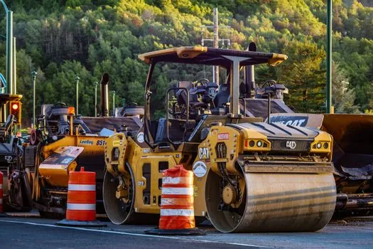
Dynamic compaction is a fit for new road construction over deep variable fills, gravel wearing-course upgrades, remediation of existing asphalt roads showing settlement, and mine haul or airport runway subgrade where a 2 m plus depth of influence is needed in one operation [S3]. It is not a fit for shallow urban street resurfacing, work within 30 to 50 m of vibration-sensitive structures, sites with a water table within 1.5 m of grade, or corridors crossing live pipelines without a project-specific vibration study [S4].
For yards that need to stage gear and consumables around a dynamic compaction campaign, a separate spec walk-through for storage rack picks for road construction yards is worth running in parallel. Where the corridor crosses port or terminal pavements, asphalt paver selection for port and terminal paving covers the surface-lift half of the same package. And where the project sits over a pipeline easement, pile driver selection for pipeline construction maps the deeper-energy neighbour that the DGMK study is trying to harmonize with road-spec practice [S4].
Specification Inputs and Trial Grid
A defensible dynamic compaction spec carries four numbers: tamper weight, drop height, grid spacing, and number of passes, each tied to a target depth of densification and a measured bearing capacity. The USDOT guideline ties applied energy to 10 to 35 ft of densification depth and to a target bearing capacity typically in the 100 to 150 kPa band for spread-footing support [S1][S5]. A pre-production trial grid with cone penetrometer or plate-load checks is the cheapest insurance on the project, and the data from that trial feeds the production grid spacing.
Two trackable signals for the next planning cycle: the DGMK research consortium at the University of Applied Sciences Oldenburg, working with MAX STREICHER, TÜV Süd, and LGA, is finalizing a standardized procedure for filling pipe trenches and road substructure in the pipeline sector through 2024 [S4]. On the equipment side, OEM impact-compactor fleets are now quoting 25 kJ per blow as a baseline rather than a stretch number, with 2 m plus depth of influence cited as standard rather than exceptional [S3]. Together these two signals point to dynamic compaction moving from specialty ground-improvement line item to a routine spec option on cross-sector infrastructure tenders.
The underlying component specifications are covered under dynamic compactor.