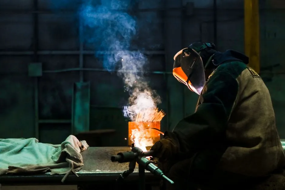
Electroslag pressure welding (EPW) is the dominant vertical-bar splice method on Chinese tunnel and high-rise sites, fusing 16-40 mm rebar end to end inside a flux-filled mold with DC current in the 200-650 A range at 35-45 V arc voltage, then applying upset pressure to forge a raised weld collar [S3][S5].
For tunnel construction, the EPW decision is driven by four locked specs: maximum bar diameter the welding head accepts, current rating and duty cycle of the power source, upset (forging) force the head can deliver, and the control sequencing of the arc stage, electroslag stage, and upset stage, with the same limits the electroslag pressure welder encyclopedia page documents for cast-in-place column work [S2][S5].
Process Envelope and Why It Fits a Tunnel Cage
EPW joins diameters from roughly 16 mm to 40 mm without a separate filler wire, producing a visible weld collar that is later ground flush before concrete placement, which is the same collar quality window that JGJ 18-2012 constrains on axial offset, bar diameter mismatch, and visible defect thresholds [S2][S5]. The cycle runs in three stages: high no-load voltage strikes an arc that melts granular flux into a conductive slag pool, current then flows through the slag by resistance rather than through an arc, and finally the welder drives the upper bar down under upset pressure to forge the joint and expel slag and oxides as a collar [S5].
In a tunnel invert or side-wall cage the head and clamp assembly is light enough for one or two workers to climb the rebar ladder, while the heavier power source stays on the deck or in the heading, connected by cables, and the same mass split is what makes EPW preferable to lap splicing when column heights run above roughly 3 m [S5]. A related plate process, electroslag welding (ESW) of thick plate, shares the slag-bath principle but uses water-cooled copper shoes and a consumable guide tube, and is mechanically impractical for the construction tools and rebar work that defines a tunnel cycle [S2][S4].
Selection Criteria for Tunnel Site Use
Four specifications must be locked before quoting on a tunnel cage: maximum bar diameter the welding head accepts (commonly 16, 20, 25, 32, 40 mm), welding current rating and duty cycle of the power source, the upset force the head can deliver to forge the bar ends, and the control sequencing of arc stage, electroslag stage, and upset stage [S2]. On a tunnel site, current capacity of roughly 200-650 A covers the full 16-32 mm range in one power source, with arc voltage U2 held in the 35-45 V window, which lets the same rig move between invert cages, side-wall lifts, and crown closure splices without a re-spec [S3].
For procurement, the practical comparison of the main options in 2026 looks like this: a manual clamp, AC transformer welder, single bar range 16-32 mm has the lowest cost and a light head, suited to small pier columns and tight headings, but operator skill drives weld-collar quality; a manual clamp, inverter DC welder, 16-40 mm range, with a programmable arc-to-upset timer carries higher first cost but more repeatable collars, which is the preferred build on tall pier lifts and tunnel sections where the worker climbs with the head [S2]. A semi-automatic dual-operator rig with a 25-50 mm range and hydraulic upset gives the best collar consistency on large-diameter bars, but it is heavier and needs crane lifts, which a tunnel heading cannot always supply [S2].
Comparison of EPW vs. Couplers vs. Lap Splices for Tunnel Work

EPW is one of three rebar joining options on a tunnel cage, and the decision is set by bar density, cycle time, and code path: EPW runs a vertical bar splice in a single flux-filled cycle with a visible collar that is later ground flush; the mechanical splice, threaded or swaged couplers, joins bars end to end without heat and is preferred where welding is excluded by spec; and the lap splice relies on overlap length to transfer load and is the slowest of the three on dense cages [S5]. On the strength axis, ACI 318 requires that welded and mechanical splices develop in tension or compression at least 125 percent of the force that would yield the bar, the same full-strength bar that the lap splice avoids by relying on overlap length, so EPW and couplers are spec-equal where welding is allowed [S5].
For comparison, the relevant rebar coupler selection for tunnel construction map lays out the same three-way trade on thread pitch, bar-end prep, and inspection cost, and EPW wins on cycle time when bars run true and the crew can stage a flux mold at every splice [S2]. On a densely reinforced invert or side-wall, the throughput gap is roughly 3-5× over lap splicing and is comparable to a swaged coupler, with the EPW saving concentrated in crane time and overlap steel rather than in splice hardware [S2][S5].
Limitations, Failure Modes, and Standards Constraints
Plate ESW, the related process, is restricted to vertical or near-vertical orientation because the molten pool and slag must be held by gravity and copper shoes, and below roughly 25 mm plate thickness the slag bath cannot be reliably established and held, so thin-gauge fabrication stays on conventional arc welder processes such as SMAW or TIG welder routines [S4]. The rebar EPW process inherits the same orientation constraint because the slag pool is held by the flux-filled mold, not by copper shoes, and out-of-position work is mechanically impractical with a standard EPW rig [S4][S5].
Coarse prior-austenite grain and a wide heat-affected zone are inherent to the slow cooling produced by the large slag mass, and on some quenched-and-tempered or alloyed rebar grades this drives HAZ hardness above the bands that sour-service or low-temperature toughness regimes will accept, which is why the documented operating window is low-carbon steel and a narrow band of structural rebar grades [S4]. Welds are also limited to low-carbon steel and standard ESW flux and parameter windows; stainless, high-alloy, and aluminum grades are not in the documented operating window for generic ESW, and the same constraint applies to rebar grade selection on EPW [S4]. On the code side, the rebar process is governed in China by JGJ 18-2012 and in the US by AWS D1.4/D1.4M, with ACI 318 splice provisions as the strength reference [S2][S5].
Fit-for-Duty Logic on a Tunnel Project

EPW is the right tool for vertical column rebar in cast-in-place tunnel side walls, invert piers, and crown closure lifts where bars run true and the crew can stage a flux mold at every splice, and where the head and clamp can be carried by hand up the rebar ladder; it is the wrong tool for horizontal mat splices in the invert, where the slag pool cannot be held, and for tightly curved bar runs where the welding head cannot clamp coaxially [S2][S4][S5]. On a tunnel with 25-40 mm vertical bars at 150-200 mm centers, a 200-650 A inverter DC unit with a programmable arc-to-upset timer is the build that pays back the extra first cost through collar repeatability, and the same rig can be redeployed to a bridge column on the next phase [S2][S3].
Trackable signals for the next purchase decision: JGJ 18-2012 collar quality limits on axial offset and bar diameter mismatch, AWS D1.4/D1.4M revisions referenced in any project specification, ACI 318-19 splice provisions on the 125 percent yield-strength requirement, and any project-specific exclusion on electroslag processes above 40 mm bar diameter, since the documented window stops at that size for generic EPW power sources [S2][S3][S5].