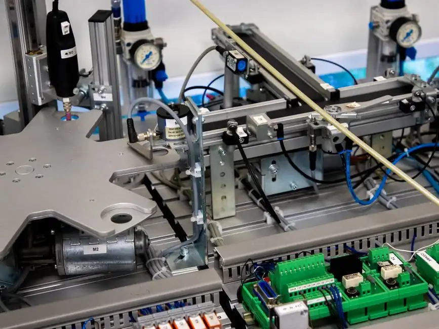
An EV traction motor production line typically strings together 8-12 stations: slot paper insertion, vertical winding, coil insertion, inter-phase forming, pre-lacing, hairpin welding, magnet loading, rotor balancing, and end-of-line encoder calibration [S6].
Throughput planning has to start from the rotor, because hairpin stator welding and PMAC magnet assembly are the two longest cycle-time stations; the rest of the line is paced to them [S5][S6].
Line Architecture and Station Sequence
Full-line layouts integrate slot paper insertion, vertical winding, coil insertion, inter-phase forming, pre-lacing forming, and final testing in a single transfer path, with each station buffered by a short pitch conveyor that absorbs single-digit-second variation between cells [S6].
For the stator side, the defining difference between a legacy round-wire line and a 2025-era hairpin line is joint count: hairpin stators replace continuous windings with individually bent rectangular-wire segments, multiplying the number of copper-to-copper welds that must pass pull-test and micro-section inspection [S5].
Rotor-side, a PMAC rotor station has to handle small, easily damaged magnets that vary in size, using flexible feeders with vision-guided robot pickup and 2-part adhesive dispense volumes held to tight tolerances [S5]. For a deeper look at how BOM choices ripple into that assembly cost, the EV Traction Motor Manufacturing Cost breakdown maps the same stations against cost drivers.
Hairpin Welding: Process Selection and Spec Window
Copper lead positions in hairpin and I-pin stators are not consistent from slot to slot, so weld gaps and torch standoffs vary part-to-part and torch-only processes cannot hold the joint quality on their own [S5].
A 3D-vision-guided high-frequency TIG cell closes that loop: it locates each lead in three-dimensional space, judges weldability, guides the torch to a position optimised for the lead condition, joins, and inspects the resulting weld in one machine cycle [S5].
Pull-test thresholds for hairpin joints are typically validated against the inverter's peak phase-current envelope rather than a generic tensile number, because joint failure under thermal cycling, not static pull, is the dominant field-failure mode. The same logic drives flat belt selection for automotive production, where the duty envelope, not catalogue tensile rating, sets the spec.
PMAC Rotor Magnet Loading and Adhesive Dispense
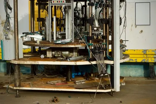
PMAC rotors are built around small, easily damaged magnets with part-to-part dimensional variation, so the cell uses high-variety flexible feeders, machine vision for robot guidance, and pre-load inspection rather than a fixed-bowl vibratory approach [S5].
Magnet-to-rotor bonding is the most failure-sensitive step, because 2-part adhesive dispense volumes are very small, mix-ratio tolerances are tight, and mixed material clogs dispense nozzles quickly if not purged on a defined cycle [S5].
Process control therefore pairs temperature-controlled supply tanks with agitation, servo-driven dual-piston dispensing heads with mixing nozzles, automated nozzle wiping, automated tip-geometry check, automated dispense-weight check, and a purge station between shots [S5]. The dispense-weight check, not cycle-time, is the cadence-setter for the rotor cell.
Encoder Feedback for End-of-Line Rotor Calibration
Traction motors need real-time rotor position and velocity feedback to control torque, efficiency, and thermal performance, which is why the final test station is built around a precision optical encoder rather than a resolver-style probe [S4].
For this duty, true-absolute encoders with 1 nm resolution, ±40 nm SDE, and sub-10 nm RMS jitter are commonly specified, with instant position acquisition at power-up so multi-head test rigs do not have to home before each cycle [S4].
Maximum tracking speed in the test rig is usually quoted at 100 m/s on the linear axis, which is well above what the rotor itself sees in service but gives headroom for back-EMF mapping at high RPM [S4]. The encoder cell is also where controller-protocol handshakes (EtherCAT, PROFINET, and the usual automotive CAN/FlexRay stacks) are burned in before the motor ships to the inverter line.
Comparing the Three Stator Approaches on Line-Build Criteria
On a greenfield line, the three credible stator architectures score very differently on the criteria that actually drive capital and cycle time. [S5]
Round-wire wound stators have the lowest joint count and the simplest winding machine, but they lose out on slot-fill and continuous-torque density, which pushes them out of 250-400 V premium-EV programmes [S1][S5].
Segmented-core / segmented-coil stators add performance by joining coils after winding, so the line has to add a separate joint-formation station and a bus-ring weld cell, but they keep using wound bobbins that are easier to source than bent rectangular wire [S5].
Hairpin and I-Pin stators win on slot-fill and thermal performance, but they require 3D-vision-guided welding, in-line weld inspection, and tight incoming control on rectangular copper, so capex per station is the highest of the three and cycle time is gated by the weld cell [S5].
Who This Line Is For, and Where It Breaks
Hairpin-plus-PMAC lines are a fit for programmes targeting continuous power density above roughly 150 kW per motor, where round-wire stators cannot meet the thermal envelope and where the OEM can absorb the higher per-station capex [S1][S5].
They are not a fit for low-volume programmes under about 30,000 units per year, because the vision-guided weld cell and the encoder calibration cell need steady volume to justify their footprint; below that band, a wound-stator line on a shared automatic molding line platform is usually the lower-risk path [S5][S6].
Common failure modes, in order of frequency seen during ramp-up, are hairpin weld defects from incoming copper tolerance drift, magnet adhesive under-cure from dispense-weight drift, and encoder test false-rejects from ground-loop noise on the eOL station [S4][S5]. A conveyor sorting line feeding reject bins is therefore not optional at scale; it is part of the station's safety logic.
Standards, Traceability, and the Next Signal to Watch

Process validation is anchored on functional tests, including back-EMF constant, phase resistance, inductance, and high-pot / insulation resistance on every motor, with statistical sampling for vibration and salt-spray on the housing [S3][S4].
The two trackable signals for the next 6-12 months are: (1) hairpin-to-bus-ring laser-welding cells replacing some of the HF-TIG cells to cut cycle time, and (2) magnet-feed cells moving from bowl-fed flexible feeders to tray-fed 6-axis cells as magnet geometry tightens for higher-speed rotors [S5]. Both shifts are driven by the same upstream constraint, which is the rectangular copper and magnet dimensional tolerance, not the welding or feeding equipment itself.
For component-level specifications, see molding line.