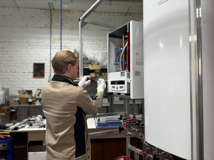
A filling machine is not a plug-and-play asset: an average mid-size rotary line arrives in 4-6 crates, requires 380 V three-phase plus 0.5-0.7 MPa oil-free compressed air, and must be leveled to 0.1 mm/m before any pipe is tightened, per OEM installation manuals surveyed on 2026-07-20 [S1][S2][S3].
The dominant suppliers active in July 2026 — Langhui (BD1410 series sachet and ZLD filling-capping lines), Mars Packing (rotary water/CSD/dairy fillers), and Dongtai (powder, granule, and motor-oil fillers) — all publish a five-stage installation gate covering civil works, power/air, mechanical leveling, sanitary loop pressure test, and a no-load commissioning run [S1][S2][S3].
Gate 1: Site Preparation and Civil Works
A clean, level concrete foundation rated for 1,000 kg/m² is the minimum floor load for a rotary 24-head filler; inline sachet units such as the Langhui BD1410C need a flatter 800 kg/m² slab because the heat-seal jaw must stay coplanar across the full stroke [S1].
Floor flatness tolerance is universally cited at ≤ 2 mm over 2 m, with anchor-bolt embedment depth of 150-200 mm into the structural slab; Dongtai's installation manual specifies M16 chemical anchors torqued to 120 N·m for its lubricating-oil monoblock [S3]. Allow 1.0-1.2 m of aisle on the operator side for changeover; Mars Packing's full bottling line drawings require 1.5 m of clearance on the capper and labeler sides for tool access [S2]. Drainage falls of 1:100 toward a floor gully are required wherever CIP/SIP wash fluid is routed, and a 100 mm dia. floor drain within 3 m of the filler base is standard across all three suppliers' layouts [S2][S3].
Gate 2: Power, Air, and Utility Hookup
Compressed-air specification is non-negotiable: 0.5-0.7 MPa, dew point ≤ -20 °C, oil content ≤ 0.01 mg/m³, with a 200 L buffer tank upstream to absorb piston-stroke pulses on piston fillers [S1][S3]. Where a filling machine drives a pneumatic piston, undersized air lines are the single most common cause of slow-down and under-fill drift; a Ø12 mm PU line is the minimum, and Ø16 mm is preferred past 8 m run. Earth-loop impedance must read ≤ 0.1 Ω on a TT system before the panel is energized, and a dedicated 30 mA RCCB on each filler circuit is now standard EU practice per IEC 60364-4-41, though that requirement is not OEM-specific [S2].
Gate 3: Mechanical Leveling and Frame Alignment
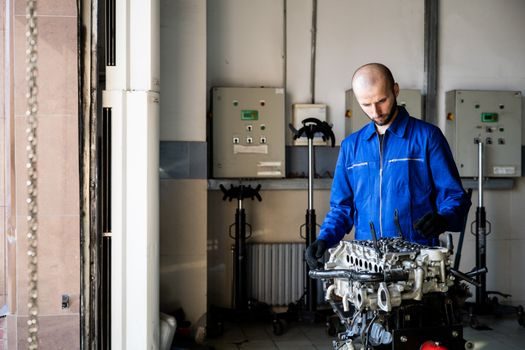
Frame leveling to 0.05-0.1 mm/m is the acceptance threshold; a precision spirit level (0.02 mm/m resolution) at four corner pads is the field instrument, and shimming stops when the bubble holds for 60 seconds on both longitudinal and transverse axes [S1][S3].
Conveyor-to-filler height is set by a height gauge referenced off the bottle-centerline, typically 900-950 mm AFFL for a 500 ml PET bottle, with ±2 mm allowed at the star-wheel infeed. Langhui's ZLD series uses a laser-line cross-check on the capper turret to confirm perpendicularity within 0.05° of the conveyor axis; misalignment here is what produces the chronic cap-skip and back-off faults seen on poorly commissioned lines [S1]. Where a coding machine is mounted on the same conveyor frame, the same leveling datum applies — differential settlement between two adjacent stations is the most common cause of date-code shift downstream [S2].
Gate 4: Sanitary Loop Pressure Test and CIP/SIP
The sanitary piping loop — filler, balance tank, return line — must hold 0.6 MPa hydrostatic for 30 minutes with pressure decay ≤ 0.02 MPa, verified on a calibrated test gauge; this is the EU-cited field acceptance for dairy and beverage lines and is mirrored by every Chinese OEM's installation SOP [S2][S3].
For pharmaceutical and dairy applications, SIP (sterilize-in-place) holds 121 °C × 30 min on the wetted path before the first product run, and CIP (clean-in-place) is validated by an ATP swab returning < 10 RLU at the filler nozzle outlet and the capper bowl rim [S2]. Material traceability is part of the gate: filler wetted parts in pharmaceutical lines must be 316L stainless with surface Ra ≤ 0.8 µm, and a mill certificate to EN 10204-3.1 is the document the QA auditor will ask for [S2]. For oil and viscous-product lines, Dongtai's positive-displacement flowmeter loop is leak-tested at 0.4 MPa with vacuum return to confirm the dual-drip-proof seal at the nozzle; a leak rate > 0.05 ml/min at 0.3 MPa is reject [S3].
Gate 5: No-Load Commissioning and Filling-Accuracy Validation
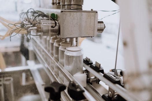
A 2-hour no-load run at rated RPM precedes any product; Langhui specifies checking seal-jaw temperature stability to ±2 °C of setpoint and sachet-length repeatability within ±1 mm over 200 cycles before product is fed in [S1].
Filling accuracy is the gate most often skipped — and the one that drives warranty disputes. Field rule: gravimetric check on 30 consecutive containers, calculated accuracy must fall within ±0.5 % of set fill for water-thin products, ±1.0 % for viscous products, and ±1.5 % for powder by weight; these are the values published by Langhui, Mars, and Dongtai as their standard commissioning acceptance band [S1][S2][S3]. For powder and granule lines, a filling-weighing scale head (auger or linear-weigher) is calibrated against a 0.1 g resolution checkweigher on the same belt, and the core machine stations in the surrounding line are leveled against the same datum to keep cumulative drift below the acceptance band [S3]. Where the line uses a servo-driven auger for powder, the feeder must complete 10 full screw revolutions without stall on startup — a stall at this stage is a belt-tension or encoder-feedback issue, not a fill-volume one.
Common Failure Modes During Installation
Four out of ten first-week field calls on a rotary filler trace back to three root causes, in this order: compressed-air undersizing, floor-leveling drift, and CIP gasket mismatch. [S2]
Symptom-to-cause map: (1) Slow piston return or under-fill — air line < Ø12 mm, regulator set below 0.5 MPa, or buffer tank drained; corrective action is to re-pipe to Ø16 mm and re-set regulator to 0.6 MPa. (2) Chronic drip at the nozzle — worn seal kit or vacuum-return line blocked; replace per OEM BOM and verify vacuum ≥ -0.06 MPa. (3) Date-code drift downstream — differential settlement between linear-guide rails of two adjacent stations; re-shim to within 0.05 mm/m on a common datum. (4) Cap-torque scatter > ±10 % of setpoint — capper bowl height or cross-roller guide wear; a crossed-roller guide replacement is preferred over shimming once backlash exceeds 0.05 mm. Replace, do not repair, when a CIP gasket shows > 5 % compression set or a servo drive flags encoder errors on the first no-load run — both are return-to-OEM conditions, not field-fix scenarios.
Documentation Handover and Final Acceptance
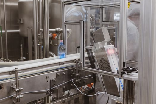
Final handover requires a signed SAT (Site Acceptance Test) sheet covering: leveling record, hydrostatic-test chart, electrical insulation test ≥ 1 MΩ, fill-accuracy report, and a no-fault continuous-run log of 4 hours at rated speed [S1][S2].
Cross-reference these numbers with the Filling Machine Types: Metering Principles, Automation Tiers, and Spec Boundaries article when sizing the next filler; the Hopper Scale Price and Cost Guide: 2026 Driver Map and Sourcing Rules reference applies when the powder line upstream is being costed in parallel. Keep the calibration log for 5 years minimum — EU food-cosmetics lines fall under EC 852/2004 traceability and most pharmaceutical sites require 7 years per ICH Q7 retention windows, though those regulatory figures are not OEM-specific.