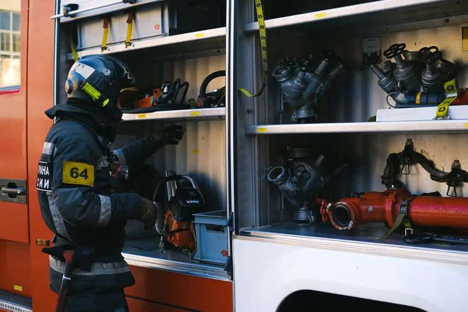
Fire hydrant selection for firefighting is a pressure-and-pipe decision first, a fittings decision second: NFPA 13 governs the water-supply curve, NFPA 1 governs hydrant spacing and clearance, and FM/UL-listed pipe and hydrants close the compliance loop [S2][S3].
The City of Tavares, Florida began a community-wide hydrant flow test on August 24, 2026, running through November 1, 2026, the kind of empirical pressure and flow data that ultimately feeds fire-protection engineering decisions and the periodic re-spec of hydrant assemblies [S1]. The same logic, static pressure, residual pressure, and Pitot reading at a flowing hydrant, drives both the field test and the procurement spec for a new hydrant on a chemical-plant or warehouse site.
Start With Pressure, Not Brand
Static pressure at the hydrant base is the single most consequential number in the spec, because it sets the upper bound for what the valve body, bonnet, and stem must hold without creeping or chattering [S6]. The selection checklist recommends recording the actual installation-point pressure before any model is shortlisted, and pairing that with the hydrant's internal head loss so the residual pressure at the outlet still meets the fire-service requirement [S6]. A typical municipal loop delivers 4–8 bar static in residential zones and 6–10 bar in industrial zones; if the project sits below 4 bar, the hydrant must be specified together with a fire pump and water tank to lift usable pressure at the nozzle [S5].
Open-under-pressure behaviour matters equally: a hydrant that requires a trench key and a strong shoulder to crack open wastes the first 10–15 seconds of an attack, and most procurement guides now require a torque-tested stem and a dry-barrel design that can be opened fully by one firefighter [S6]. For systems fed by pump discharge lines that can exceed 16 bar, the upstream main should be seamless steel rather than ERW, because water-hammer transients on rapid valve closure concentrate stress on the longitudinal weld zone of ERW pipe [S4].
Seamless vs ERW: Where Each Pipe Earns Its Place
Seamless steel pipe is the default for any run where the operating pressure exceeds 16 bar (232 PSI), including pump discharge headers, the riser between the check valve and the hydrant isolation valve, and any section feeding a dry-barrel hydrant in a high-rise riser [S4]. Its lack of a longitudinal weld seam removes the failure mode most often seen in post-incident investigations, namely weld-zone cracking after repeated pressure cycling.
ERW (Electric Resistance Welded) pipe is the cost-optimized choice for distribution branch lines that run from the main header to individual hydrant outlets, where pressures are lower and the run length dominates material cost [S4]. ERW pipe is acceptable provided the internal weld bead is removed or smoothed (a frequent procurement note), the line is hydrostatically tested, and the line carries FM or UL listing for fire service [S4]. The project economics are real: a 1 km branch in ERW instead of seamless can save 15–25% on material, which compounds across a multi-hydrant campus.
External Coating and Internal Lining Decide the 25-Year Outcome
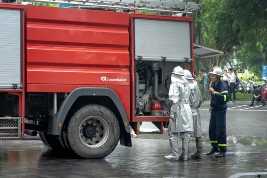
Underground fire hydrant mains live or die by their external coating, because the cost to excavate a paved road, repair a leak, and re-pave typically runs around ten times the original pipe cost [S4]. 3LPE (three-layer polyethylene) coating is the current default for direct-buried fire mains in most soil conditions, with bonded epoxy primer, adhesive copolymer, and a PE topcoat forming a combined film thickness of roughly 2.0–3.0 mm. Internally, a fusion-bonded epoxy (FBE) lining of 250–400 microns keeps tuberculation and valve-clogging debris out of the hydrant lateral, which directly protects the fire hydrant main seat and stem packing.
For above-grade portions of the hydrant body, the standard spec is a ductile-iron body to ASTM A536 Grade 65-45-12 with a fusion-bonded epoxy interior and a polyester exterior coat, and a bronze or brass trim set for the valve stem, seat, and drain ring. The trim is the part that determines whether the hydrant can be opened under full mains pressure without a specialty tool, which is the third leg of the field checklist [S6]. For more on the wider fire-system envelope, the fire safety reference page collects the governing codes for the rest of the suppression chain.
Spelling Out the Sizing Criteria
Three criteria do most of the work in a defensible hydrant selection: (1) static pressure at the point of installation, (2) head loss across the hydrant body at the design flow, and (3) clearance from structures and vegetation per NFPA 1 [S2][S6]. A hydrant installed within 15 feet of a building or behind a shrub line is functionally inaccessible to a 200-foot hose lay, regardless of how clean its internal head-loss curve looks on paper [S2].
For typical industrial and commercial projects, the minimum combined flow target is 1,000–1,500 GPM at 20 PSI residual for the dominant structure, and the hydrant spacing to hit that target is roughly 300–500 feet in light-hazard occupancies, tightening to 250–350 feet where storage heights exceed 30 feet [S3]. Australian projects under NCC 2025 face an equivalent trigger: AS 2419 hydrants are required once the floor area or building height crosses the AS 2118 threshold for sprinkler-only coverage, and a parallel hydrant riser is added to serve the hose lay [S7]. A practical side-by-side of the main pipe choices: Seamless steel is the right call for high-pressure headers and pump discharge (above 16 bar), ERW is the right call for branch distribution up to 16 bar, and ductile-iron with FBE lining is the right call for the hydrant barrel and above-grade fittings.
Field Testing Closes the Loop
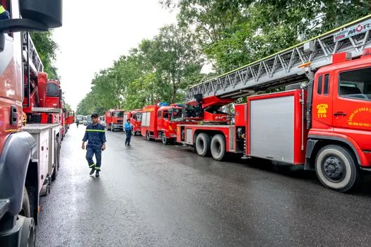
Hydrant flow testing translates measured static, residual, and Pitot pressures into a defensible water-supply curve, and is the empirical input every designer needs before sizing a new hydrant or signing off on a main extension [S3]. The standard field kit includes a pressure gauge on the residual hydrant, a Pitot gauge on the flowing hydrant, and a diffuser on the discharge to keep water out of the street and landscaped areas, an arrangement that matters in tight urban sites where a 1,000 GPM stream would otherwise flood a neighbor's yard [S3].
Results should be plotted using the Hazen-Williams or Darcy-Weisbach form of the hydraulic graph, then read against the required fire flow at 20 PSI residual to confirm available supply, the same comparison a spec writer uses to decide whether the chosen hydrant will actually deliver under incident conditions [S3]. Routine flushing, the kind Tavares is running through November 1, 2026, also helps reveal tuberculation or closed valves that quietly degrade the system long before a fire starts [S1].
Where Selection Goes Wrong
Three failure modes dominate post-incident reviews. First, a hydrant is installed at low static pressure with no pump and no tank, so the nozzle stream collapses below usable attack pressure the moment a second hydrant is opened. Second, ERW is used on a pump discharge line where water hammer is routine, and the weld zone fatigues within a decade. Third, a hydrant is buried behind landscaping or parked cars, defeating the very flow test that justified its position, the exact access problem NFPA 1 clearance rules around fire hydrants are written to prevent [S2].
For indoor layouts, a separate failure mode is specifying a wet-barrel hydrant in a climate where the barrel can freeze, which ruptures the body and disables the riser until a full replacement, an avoidable outcome covered in the fire door and fire-rated door family of references only by analogy, but worth flagging here because the freeze-damage pattern is the same as for any pressure-rated water-filled assembly. The mitigation is a dry-barrel design with an automatic drain that empties the barrel when the valve is closed, specified together with a bury depth below the local frost line.
For related coverage, see Strapping Machine Selection for Chemical Shipping: PET, Steel, and Matched Sealing.