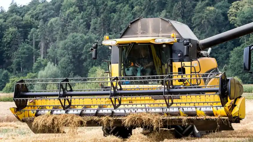
Agricultural drivelines on tractors, balers, feed mixers, grain augers, and large PTO-driven implements typically pair a fluid coupling between a squirrel-cage motor or diesel engine and a high-inertia load; correct sizing rests on motor kW, peak starting torque, and the inertia ratio between driver and driven machine [S3].
A fluid coupling is a hydrodynamic, non-contact torque transmitter built around a centrifugal pump wheel and a turbine wheel housed in a sealed shell, using mineral hydraulic fluid (commonly ISO VG 32) as the working medium; because there is no mechanical contact, the unit slips under overload rather than fracturing, which is the core reason it is specified for agriculture machinery exposed to crop slug-loading and plug-ups [S5][S7].
Agriculture Driveline Profiles: Why a Fluid Coupling, Not a Jaw or Gear Coupling
Agricultural applications span constant load (centrifugal irrigation pumps, aeration fans), variable load (grain elevators, augers, conveyors, feed mixers), and shock load (hammer mills, chaff cutters, sugar-cane crushers), and the load profile drives the coupling architecture, not vice versa [S1]. Soft-start, torque-limiting, and overload-slip behaviour are the three engineering reasons to prefer a fluid coupling over a jaw coupling (rigid in torsion, good for alignment only) or a gear coupling (high torque capacity but transmits shock directly to the gearbox) when the driven implement is a high-inertia rotor [S3][S4].
For conveyors and bucket elevators in grain handling, the smooth torque ramp of a fluid coupling protects the belt from the snap-load that an elastomeric or grid coupling would simply forward to the next weakest link; the same logic applies to roller presses, mixers, large ventilators, and crusher rolls in feed and biomass plants [S3].
Sizing Inputs: kW, RPM, Service Factor, and Inertia Ratio
The minimum inputs every manufacturer requires are motor nameplate kW (or HP), motor RPM, driven-machine RPM, service factor, and the inertia of the driven rotor, because fluid coupling heat capacity is governed by slip energy, and slip energy is governed by the mismatch between driver acceleration and load acceleration [S3][S7]. With a squirrel-cage induction motor, the fluid coupling allows a near-unloaded acceleration of the motor and a slow, controlled ramp of the load, which simultaneously limits starting current draw and avoids grid overloading when multiple motors start together [S3].
Variable-fill designs from Voith cover 100 kW to 35 MW, which brackets essentially every agricultural driveline from a mid-size feed-mill motor to a sugar-mill cane carrier drive, while constant-fill units dominate the sub-500 kW segment typical of on-farm and primary-processing equipment [S2]. Service factor selection follows the same logic as gear coupling selection: 1.0 for uniform load, 1.25-1.5 for variable load, and 1.5-2.0 or higher for shock load with frequent plug-ups [S1].
Constant-Fill vs Variable-Fill vs Delay-Chamber Couplings
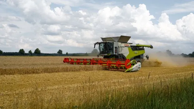
Constant-fill couplings hold a fixed charge of oil and transmit torque proportional to the square of input speed; they are the lowest-cost option and suit steady-state applications such as centrifugal pumps and aeration fans where the motor is sized close to the load and plug-ups are rare [S1][S6].
Variable-fill (also called scoop-control or fluid-controlled) couplings use an external actuating scoop or servo to vary the working fluid volume during run-up, which lets the operator tune start time, peak torque, and slip independently of motor kW; Voith specifies this architecture for pump, fan, and compressor speed control across the full 100 kW to 35 MW envelope [S2].
Delay-chamber (or "quick-start") couplings add a secondary chamber that releases fluid only after a set delay, giving a near-empty start for very high-inertia loads and then filling the working circuit for normal running; these are commonly specified on belt conveyors, bucket elevators, and chain conveyors where the empty-belt acceleration should be fast and the loaded-belt acceleration slow [S3].
Working Fluid, Slip, and Thermal Limits
Slip, defined as (input RPM minus output RPM) divided by input RPM, typically runs 2-5 percent at rated load in a correctly sized fluid coupling, and slip energy shows up as heat in the working fluid, so thermal capacity is the hidden sizing constraint, not torque capacity [S5][S6]. Mineral HLP hydraulic fluid at ISO VG 32 is the standard charge; in grain-storage or fire-risk environments, HFA water-oil emulsion, HFD-U water-free flame-resistant synthetic, or biodegradable synthetic-ester fluids are used instead, with HFA limited by cavitation tendency and a tighter temperature window [S5].
Overheating is the most common failure mode of a wrongly specified unit, particularly when the coupling is run outside its rated kW band or in a poorly ventilated enclosure, and it shows up first as accelerated seal hardening and then as bearing distress, since only the antifriction bearings and seals see mechanical wear in a hydrodynamic unit [S1][S5].
Selection Criteria for Common Agricultural Implements
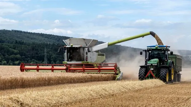
For grain augers, belt conveyors, and bucket elevators, the load is essentially constant once filled, but the start is the hard part, so a constant-fill or delay-chamber coupling sized at 1.0-1.25 service factor is normally adequate; for feed mixers, crushers, and roller presses where the load varies with material density, a variable-fill coupling at 1.25-1.5 service factor is the conservative call [S1][S3].
For chaff cutters, hammer mills, and sugar-cane shredders facing sudden slug loads, a fluid coupling should be treated as a sacrificial torque limiter: specify the coupling so its slip torque sits below the gearbox rating, accept higher slip, and verify that the coupling's continuous-thermal rating covers the worst-case plug frequency, since repeated slip events stack heat in the charge oil [S1][S3]. The same driveline-protection logic that drives a fluid coupling on a mining conveyor applies to agricultural conveyors, and the comparison between fluid, elastomeric, and metallic coupling families for shock load is laid out in the fluid coupling selection for material handling reference.
Interaction with Gearbox, Belt, and Chain Drives
On a tractor-driven or motorised implement the fluid coupling is rarely the only flexible element; it normally sits between the prime mover and a gear coupling or chain drive feeding the implement gearbox, and the chain drive selection for the downstream implement follows its own pitch, series, and attachment logic as covered in the conveyor chain selection for agriculture machinery reference [S3][S4].
Misalignment accommodation is not the fluid coupling's job; hydrodynamic units tolerate minimal parallel or angular offset, so a disc coupling or short jaw coupling is usually placed downstream of the fluid coupling to handle residual misalignment, with the fluid coupling kept as close to the motor as possible to keep the input shaft short and stiff [S3][S4]. Mounting style (foot, flange, vertical-shaft) must match the driven machine's shaft orientation, and most agricultural units use foot-mounted constant-fill housings for ease of belt-drive alignment [S1].
Who Should Specify a Fluid Coupling, and Who Should Not
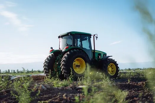
Fluid couplings earn their place on agricultural drivelines with high starting inertia, frequent load surges, or strict no-start-spike requirements, including grain conveyors, mixers, crusher rolls, large fans, and pump sets on shared electrical buses; they do not earn their place where precise speed holding under varying load is required (use a VFD or variable speed drive instead), where the driven machine needs positive torque transmission at zero slip (use a clutch or torque converter with lock-up), or where the duty cycle is light and a simple jaw coupling will survive [S2][S4][S6].
They are also a poor choice in explosion-risk grain-handling enclosures unless the working fluid is rated for the hazard class, because a hot slip event in an HLP-mineral unit is an ignition source, and the HFD-U or synthetic-ester flame-resistant fluids exist specifically for this case, though at higher cost and tighter viscosity control [S5].
Maintenance and Failure-Mode Watch List
Maintenance is dominated by fluid condition (sample the oil for viscosity break-down, water ingress, and particulate), seal integrity (visual check for weeps at the input and output shaft seals), and bearing condition (vibration and temperature trending); the construction, working, operation, and maintenance of fluid couplings reference covers the full inspection cadence from daily checks through annual oil analysis [S3][S5].
Three failure modes account for most agricultural fluid-coupling replacements: thermal overload from chronic over-filling or under-filling (oil level is the primary tuning parameter, not an installation detail), seal failure from contaminated or aged fluid, and bearing failure from radial load being fed back into the unit by a misaligned downstream coupling [S1][S3][S5].
Standards and Sourcing Reference
No single ISO or API standard governs agricultural fluid-coupling selection the way API 610 governs pumps; manufacturers publish their own rating curves and service-factor tables, and the practical cross-reference is the OEM's kW-versus-slip and thermal rating curves for the specific housing size [S1][S2][S3]. For European OEM sourcing, the Voith variable-speed product line and the Transfluid industrial product line are the two most-cited references for the 100 kW to 35 MW and sub-1 MW agricultural segments respectively [S2][S8].
Track the following signals over the next planning cycle: (1) ISO VG 32 mineral-oil versus HFD-U synthetic-ester take-up in grain-storage OEMs as a leading indicator of ignition-risk mitigation; (2) variable-fill versus constant-fill shipment mix as a leading indicator of soft-start requirements in mid-size agricultural conveyors; and (3) bearing-temperature alarm thresholds in OEM service manuals, which is where overheating failures actually show up before seal failure does [S1][S3][S5].