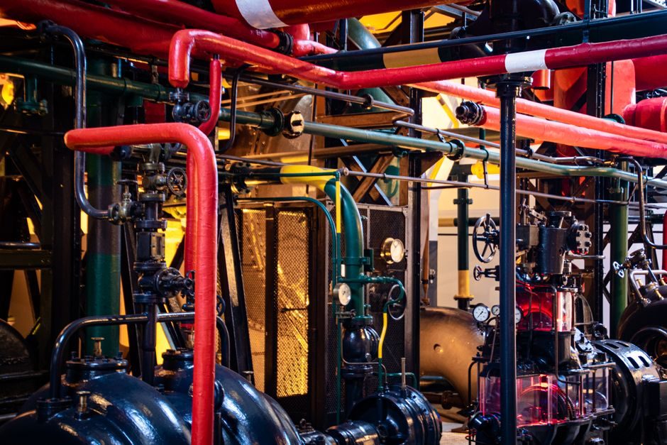
For industrial soft-start duty, size the fluid coupling on absorbed kW multiplied by an SF 1.0–1.5 service factor, verify thermal capacity on continuous-fill slip duty, and confirm explosion-protection class (ATEX 2014/34/EU, IECEx) before accepting a vendor proposal.
This map covers how a fluid coupling actually transmits torque, where it is the right call versus a jaw coupling, gear coupling or disc coupling, and which spec gates (power, slip, fluid, certification) separate a working selection from a return-to-vendor incident.
What a fluid coupling is — and what it is not
A fluid coupling is a hydrodynamic device with an impeller (input) and a runner (output) inside a sealed housing, transmitting torque solely through the momentum exchange of working fluid (typically ISO VG 32 mineral oil); there is no mechanical contact between input and output, so wear is limited to bearing and seal life [S1]. The defining behavioural fact is slip: at 100% load the output shaft turns roughly 1.5–5% slower than the input, and that slip is what dissipates energy as heat. That is also why a fluid coupling cannot be a precise positioning device — the slip is load-dependent, not a fixed ratio.
Compare that to a jaw coupling (elastomer spider in compression, zero slip, failsafe on overload) or a disc coupling (laminated metal packs in torsion, zero slip, high torsional stiffness). The fluid coupling's unique value is controlled torque transmission during start-up: input ramps up, the un-loaded runner gradually takes up load, and the driven machine sees a soft, cushioned acceleration. The torque converter used in automatic passenger-car transmissions is the same hydrodynamic principle in a different packaging [S4].
Selection criteria, in the order a real spec sheet asks them
Step 1: driven machine absorbed power (kW or HP) at the coupling's rated input speed. Step 2: service factor (SF) — light uniform load like a fan or centrifugal pump often needs SF 1.0–1.25; heavy shock load like a crusher, apron feeder or high-inertia conveyor typically needs SF 1.25–1.5, sometimes up to 1.75 per AGMA-style derating tables. Step 3: thermal rating — slip power (input kW × slip fraction) becomes heat that the housing must shed; on continuous-slip duty (e.g., fluid coupling used as a speed limiter, slip 10–20%) the cooling circuit is no longer optional. Step 4: ambient and fluid — most industrial units are rated for −20 °C to +80 °C ambient with ISO VG 32 mineral oil; below 0 °C the fluid's viscosity jumps and the unit may need a low-viscosity fill or an internal heater. [S1]
Step 5: hazardous-area classification. Underground coal duty requires IECEx / ATEX group I M2; surface chemical duty typically ATEX 2014/34/EU category 2 (zone 1) for the coupling body and any integral temperature/pressure switch. Step 6: bore and mount — keyed bores, imperial or metric, plus the option of a brake drum / disc, backstop, or input/output flange; this is the lever that drives the long-tail BOM cost. Specifying all six cleanly up front is the difference between a one-pass PO and a 12-week delay.
Fluid coupling vs the alternatives: a criteria comparison

On a decision matrix with four criteria — soft-start, overload protection, zero-backlash precision, and intrinsic explosion safety — a fluid coupling scores high on soft-start and overload, but mid on explosion safety (it depends on certification) and low on zero-backlash precision because of the inherent 1.5–5% slip. A jaw coupling is the opposite: zero slip and zero backlash, but it has limited overload capacity (the elastomer spider yields at ~150–200% rated torque depending on Shore hardness) and no soft-start at all. A gear coupling handles much higher torque per envelope (often 2–4× the kW/cm³ of a fluid coupling) at the cost of needing lube and a guard; a disc coupling gives high torque in a small envelope with zero maintenance but no soft-start either. So: if your problem is "start a 250 kW crusher without tripping the motor" the fluid coupling is the right answer; if your problem is "transmit 250 kW with zero backlash on a packaging line" it is the wrong answer. [S2]
Where fluid couplings actually pay back
The high-value duty list is short and specific: long, fully loaded belt conveyors in mining and bulk handling (multiple drives sharing load through fluid couplings, each slipping a few percent so the system self-balances), cement and aggregate crushers, large fans and blowers on start, and any motor where the kVA draw during DOL start would trip a generator or weak grid. The classic reference for these power-transmission packages is the AGMA rating conventions (AGMA 9003, 2010 series), which most coupling vendors tabulate into their catalogues. [S3]
Outside that list the fluid coupling is a poor fit: it cannot be used as a holding brake, it is not a precision element, and on reversing duty the fluid churn kills efficiency. For yard logistics equipment — telehandlers, rough-terrain forklifts, concrete mixer trucks — the soft-start question is solved at the drivetrain level (torque converter, wet clutch, VFD), not at a coupling in the line shaft; readers sizing those machines will find the actual decision gates in the telehandler price and cost guide and the concrete mixer truck selection guide, not in a fluid-coupling datasheet.
Limitations, failure modes, and field returns
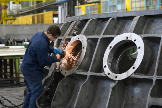
Three failure patterns dominate the field. (1) Thermal overload on long acceleration ramps — the housing gets too hot, the seal fails, the fluid degrades. Mitigation: vendor's published "max slip-second" or "max starts per hour" curve, and a temperature switch wired into the trip circuit. (2) Wrong fill — under-filled units slip more, over-filled units lose soft-start and overheat the bearings. Most vendors stamp the exact litre fill on the nameplate; a 10% deviation is a warranty dispute. (3) Bearing and seal wear on misaligned shafts — fluid couplings tolerate angular misalignment better than parallel offset (typical 0.1–0.2 mm parallel, up to 0.5° angular), but coupling misalignment is the single biggest source of unplanned stoppages. Always insist on laser alignment, not feeler gauge, at commissioning. [S4]
Standards, sourcing tiers, and procurement signals
Spec the unit to AGMA 9003 / ISO 6337 conventions for rating, ATEX 2014/34/EU or IECEx for hazardous areas (the right category depends on zone, not on a generic "explosion-proof" claim), and to the driven equipment's own standard (e.g., API 610 for pumps, API 617 for compressors) where it exists. On the BOM line item, three checks separate a working supplier from a re-badged trade unit: (a) a published continuous-slip thermal curve, not a single-point rating; (b) a documented fill procedure and a nameplate-stated fill volume; (c) bearing and seal part numbers that are common cross-references (SKF, FAG, Timken), not OEM-proprietary. Two trackable procurement signals to watch on a 2026 enquiry: lead time on cast housings (still 14–22 weeks at most EU foundries) and the availability of low-flambility fluid (ISO VG 32 HF-DR) for underground coal and surface group I duty. [S1]