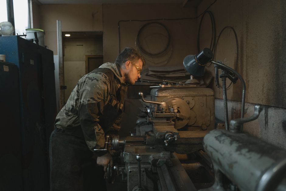
Forging presses divide into three principal machine families — mechanical, hydraulic, and screw — distinguished by how they store and deliver forming energy, with nominal force spanning 7,500 kN to 50,000 tons across the installed base [S3][S4][S10].
Presses sit alongside hammers as the second major group of forging machinery, applying continuous squeeze pressure rather than discrete impact blows, which makes them the preferred tool for tolerance-critical, long-stroke, and large-section work [S7].
Mechanical Presses: Energy-Bound Strokes at High Cycle Rates
Mechanical forging presses use a ram driven through a crankshaft or eccentric, storing kinetic energy in a flywheel, and they typically deliver higher stroke rates than any other press class [S5].
Farina's GLF series specifies nominal forces from 7,500 kN (GLF 750V) up to 20,000 kN (GLF 2000V), with continuous stroke rates of 85–110 RPM and slide strokes of 200–300 mm; thermal-limited stroke rates drop to 15–30 RPM unless a KERS energy-recovery module is fitted, in which case the thermal ceiling returns to 30 RPM across the 1,300 kN and larger models [S4]. The 10–16 mm slide adjustment window is the operator's fine-tuning band for die setup.
Mechanical presses suit high-volume closed-die hot forging where cycle time dominates cost; the energy-bound stroke profile means the deepest part of the die cavity receives the peak force only at bottom-dead-centre, which constrains deep-draw geometries [S5][S4].
Hydraulic Presses: Full-Force, Full-Stroke, Any Position
Hydraulic presses deliver constant force over the entire stroke through a piston and cylinder, and they are the only class routinely built above 10,000 tons of nominal force [S3][S10].
India's 2024 open-die hydraulic press specification requires a 3,000-ton nominal unit paired with two 20-ton rail-bound manipulators, and lists seven hot-forging operations — cogging, swaging, upsetting, planishing, smoothing, shearing, and stepped-shaft straightening at 500–550 °C — that a hammer cannot do as cleanly [S3]. The 50,000-ton Mesta press at Alcoa, built for the U.S. Air Force after a 30,000-ton German press captured in World War II, remains one of the largest fabrication tools in the world and produced the large extrusions and die forgings that supported the post-1950 Heavy Press Program [S10].
Hydraulic presses are the correct choice for open-die work, large-diameter rotor forging, isothermal forging, and any part where the workpiece geometry changes over a long ram travel; they sacrifice cycle rate for force density and stroke flexibility [S3][S5].
Screw Presses: Energy-Bound Impact with Precision Control
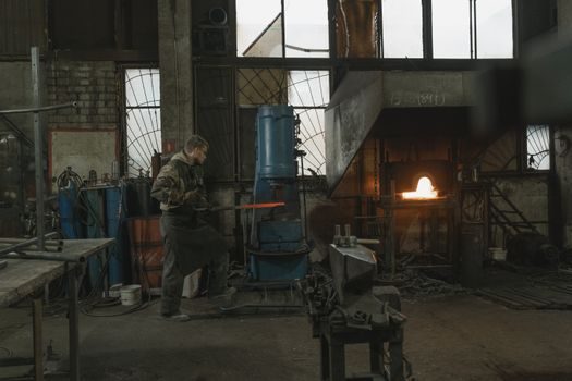
Screw presses store energy in a flywheel that drives a vertical screw, converting rotational energy into a downstroke forging blow, and SMS group markets them as "high forming force meets forging precision" [S6].
Two sub-types exist — screw presses with a continuously revolving flywheel and integral clutch, and screw presses with direct-drive — and the energy-bound nature of the stroke lets the operator control forming energy per blow by varying the clutch engagement angle, a feature no other press class offers [S6].
Screw presses dominate closed-die forging of mid-volume, mid-complexity steel and aluminium parts where energy per blow must be tuned part-to-part without changing the mechanical setup; the up-and-down material-topping FP-G design additionally reduces die-cavity inclination to minimise flash and material consumption [S8].
Process Layout Comparison: Press vs Hammer vs Other Methods
Drop forging (open-die and closed-die), press forging, upset forging, automatic hot forging, and roll forging form the principal process branches, and the equipment choice — hammer or press — sets the cost and tolerance ceiling for the part [S9].
Vertical counterblow hammers, where both top and bottom die move simultaneously, hold the largest hammer sizes; mechanical, hydraulic, and screw presses form the second group, each with a different force-stroke signature [S7]. For forging-press selection specifically, the criteria-based comparison lines up cleanly: mechanical presses lead on stroke rate (up to 110 RPM) and part-per-hour throughput, hydraulic presses lead on nominal force (1,000–50,000+ tons) and full-stroke constant pressure, and screw presses lead on energy-per-blow tunability for closed-die precision [S4][S6][S10]. For high-cycle industrial automation lines, engineers may also reference the PLC control layer that sequences die lubrication, manipulator travel, and stroke initiation across all three classes.
Application Selection Map: Which Press for Which Part
Forged-part geometry — length, section thickness, tolerance, and material flow length — is the dominant selection variable, with the press family chosen to match the longest required material travel under peak force [S7][S3].
Long shafts, stepped rotors, and large ring-rolled preforms route to open-die hydraulic presses (1,000 tons and up) because only hydraulic pressure holds full force at the long stroke end [S3]. High-volume automotive connecting rods, gears, and constant-section lever arms route to mechanical or screw presses, where cycle rate and closed-die repeatability dominate the cost model [S4][S6]. Aerospace and defence titanium bulkheads, aluminium wing fittings, and large aluminium structural extrusions route to the 10,000–50,000-ton hydraulic class, where the press becomes a national-asset-scale capital tool [S10].
Part-temperature window also matters: hot forging at 500–550 °C for straightening and 1,200 °C+ for cogging both run cleanly on hydraulic presses, whereas cold and warm forging of small precision components typically use mechanical knuckle-joint and eccentric presses outside the forging-press strict definition [S3][S7].
Failure Modes, Limits, and Cross-Process Sourcing Signals
Mechanical presses fail at the clutch and brake linings when continuous stroke rate is exceeded; thermal-rated stroke must be respected or the flywheel and bearings overheat, and KERS retrofit is the documented mitigation path on the GLF class [S4]. Hydraulic presses fail at the cylinder seals and intensifier valves under sustained high-tonnage cycles, and the manipulator-rated tonnage (here 20 tons per unit for a 3,000-ton press) sets the practical workpiece-handling ceiling regardless of press force [S3]. Screw presses fail at the thrust bearing and clutch under off-centre loading, which is why direct-drive variants exist for heavy, asymmetric closed-die work [S6].
Engineers cross-referencing forging-press controls to upstream flow and pressure instrumentation can use the pressure transmitter and flow meter encyclopedia entries to spec the hydraulic and lubrication circuits that feed each press class. For press lines that integrate pneumatically actuated clamps and gates, the industrial valve reference covers the directional and proportional valves most builders pair with the press hydraulic unit.
The next signal to watch is OEM release of KERS-equipped mid-tonnage (1,000–2,000 kN) mechanical press lines for Tier-1 automotive closed-die work, where the thermal-stroke uplift from 15 RPM to 30 RPM changes the press-vs-hammer economics for high-mix sub-1 kg parts [S4][S7].
This topic is covered further in Shock Absorber Sizing, Mounting, and Acceptance Test.