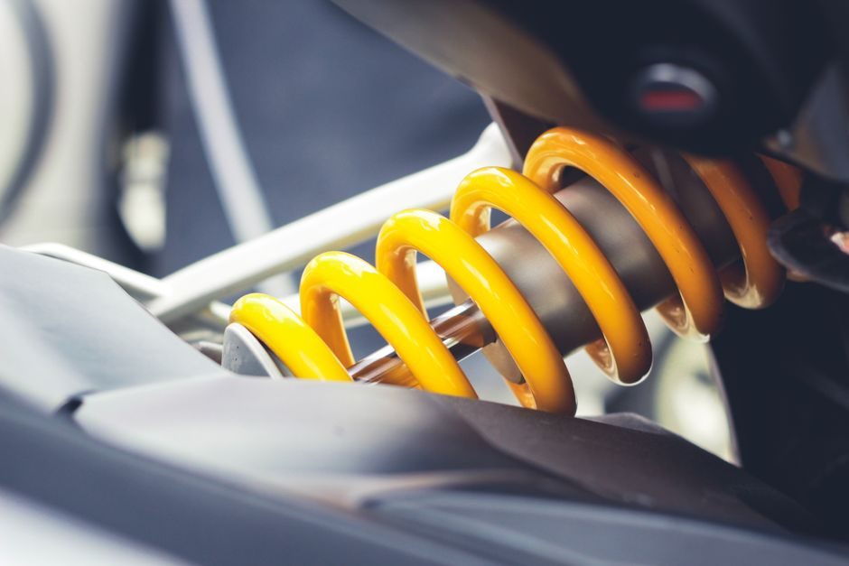
Industrial shock absorbers convert kinetic energy of a moving mass into heat through an internal orifice-and-piston hydraulic circuit, sized to dissipate a fixed amount of energy per cycle in joules without bottoming out or overheating [S1][S2][S3].
The installer's job is straightforward in concept — match the absorber's energy per stroke (E), effective mass (m), and impact velocity (v) to the moving load, then verify torque, stroke usage, and thermal envelope on the bench before the line goes live [S1][S2].
Define the load: mass, velocity, energy per cycle
Three inputs drive every selection: effective moving mass in kg, impact velocity in m/s at the moment of contact, and cycles per hour (which sets the average heat-rejection duty) [S1][S3]. Translational kinetic energy E = ½·m·v² must be less than the absorber's rated energy per stroke, and the per-hour figure must be less than its rated energy per hour, otherwise the unit overheats and damping force drops off as oil viscosity falls [S1][S3].
For a rotary index table or a swing-arm stopper, the equivalent mass is the reflected inertia at the impact point, not the motor nameplate — measure or calculate the reflected value, and add the mass of any fixture, bracket, or gripper that travels with the moving part [S1]. When in doubt, instrument the line with a load cell or accelerometer on the first build, because field mass figures diverge from CAD mass by 10–20% on real production lines [S1].
Compare the four working types against real use
Industrial dampers split into four functional families, each tied to a velocity band and a duty profile [S1][S2][S3]: (1) mechanical/urethane-bumper — pure elastic recovery, no orifice, cheapest, used where bounce-back is acceptable and impact energy is low; (2) adjustable hydraulic (KOBA KHA series and equivalents) — orifice is tuned via a 0–180° adjustment dial, damping force is varied to match impact velocity, the workhorse for robotics and packaging [S1][S2]; (3) self-compensating hydraulic — orifice area varies automatically with piston speed, used where impact velocity drifts across a wide band [S2]; (4) spring-damper with hard-stop — modeled in MATLAB/Simscape as a composite of translational spring, damper, Coulomb friction, and hard stop, dominant in OEM simulation and HIL test benches [S3].
On the four criteria a specifier actually uses — cost, velocity range, tunability, and predicted life — mechanical bumpers win on cost and simplicity but lose on tunability and energy density; adjustable hydraulic units sit in the middle on cost and lead the field on energy density per cubic centimetre; self-compensating units cost more but absorb velocity drift without re-tuning; spring-damper-with-hard-stop blocks live mostly in the simulation domain, not on the factory floor [S1][S2][S3].
Match the absorber to the application envelope
KOBA's KHA64-100 mechanical/adjustable unit is rated at 45 N load capacity, 100 mm stroke, M64 thread, with standard impact velocity 0.3–5.0 m/s and operating temperature -10 to 80 °C, optionally -40 to 120 °C with special oil and seal [S1]. The KHA115-100 self-compensating variant raises load capacity to 178 N at the same 100 mm stroke, sharing the same temperature window and velocity band, suiting heavier industrial robot end-effectors and crane safety devices [S2].
Common industrial fits listed by the manufacturer include industrial robots, packing machines, looming machines, machine tools, automobile and tire manufacturing lines, casing facilities, cranes, and safety stops [S1][S2]. For very low-velocity stops — conveyor diverters, slow indexing tables — specify the low-velocity model covering 0.08–1.3 m/s, otherwise the orifice is nearly closed at low speed and the unit behaves like a rigid stop, transmitting shock back into the frame [S1].
Mounting, alignment, and stop-collar practice
Threaded-body absorbers should be torqued against a flat, machined face with the axis perpendicular to the moving load within ±1° to avoid side-load on the piston rod and premature seal wear [S1]. The piston rod is hardened stainless steel; the bearing protecting the seal is a special low-wear grade, but only the rod — never the body — should carry the side load, and the manufacturer specifies that a bumper head can replace a separate stop collar, while a poly pad or urethane cap reduces impact noise [S1].
Set the absorber so it uses 60–80% of its rated stroke at full load impact, leaving 20–40% as a safety margin against mass growth, supply-air drift, or product variation on a real line [S1][S3]. When a hard-stop boundary is present — the Simscape block models this with upper bound UB and lower bound LB positions plus hard-stop stiffness k_HS and damping b_HS — the same logic applies: the hard stop is a mechanical backstop, not the primary energy absorber [S3].
Environment, materials, and when to escalate
Standard hydraulic oil and seals rate -10 to 80 °C; outside that band the manufacturer requires special oil and seal kits to reach -40 to 120 °C [S1][S2]. For powder-metallurgy rod guides used inside the absorber, MPIF 35 FC-0205 (DIN 30910 Sint C10 equivalent) at HRB 40–100, with optional PTFE DP4 sliding bushing and black steam oxidation, is the typical sintered bushing spec for the bearing surface [S4].
Do not try to repair a unit that has bottomed out repeatedly, leaked oil past the rod seal, or lost damping force after a thermal event — replace the complete absorber and inspect the drive for the root cause (over-mass, over-velocity, mis-alignment, or excessive cycle rate) [S1][S2]. For an adjustable hydraulic unit, a documented commissioning step is to run three no-load cycles and rotate the adjustment dial 0–180° while watching for smooth deceleration across the full stroke; if the piston reaches the end of stroke hard, increase damping; if it stalls early, decrease damping [S1][S2].
Acceptance test and trackable signals
On the bench, the acceptance check is a measured deceleration profile plus a temperature rise test: stroke the unit at rated energy for the rated cycle count, confirm the rod returns to full extension under its own spring within the published recovery time, and confirm the body temperature stabilises below the oil's continuous rating [S1][S3]. Simscape's hard-stop model offers a useful mental model — set hard-stop stiffness k_HS to a finite value, hard-stop damping b_HS to absorb residual energy, and Coulomb friction force to zero when the goal is HIL simulation rather than fidelity [S3].
For commissioning on a real machine, the simplest tracked signal is the counter on the cycle-hour meter versus the manufacturer's rated energy-per-hour figure — if the line runs above that, the absorber is undersized regardless of bench-test pass [S1][S2]. On the design side, KOBA CO., LTD is exhibiting at InnoTrans 2026 in Berlin, Hall 1.2 Stand 440, 22–25 September 2026, which is a trackable signal for new catalog data on heavy-duty rail-adjacent applications [S1][S2]. For damping hardware used in indexing tables and packaging lines, see how energy density maps onto electric ball valve selection duty ratings and onto fluid coupling installation alignment practice, both of which share the same torque-vs-stroke logic as a threaded-body shock absorber. The general shock absorber reference sits alongside related motion-control categories such as linear guide and crossed-roller guide for the upstream guidance that determines the impact angle the damper actually sees.