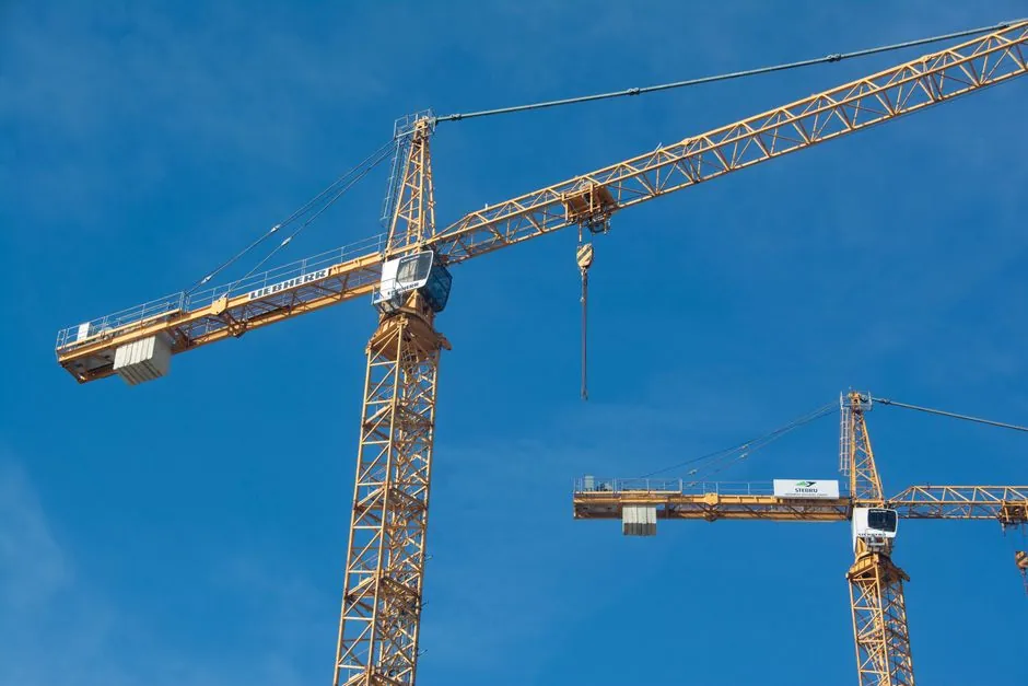
Free-standing and tied-in tower cranes are not competing models but two different support arrangements of the same ASME B30.3 equipment class, and the choice is driven by building height, foundation footprint, and wind exposure rather than by lift capacity alone [S1][S5].
ASME B30.3 explicitly categorizes a freestanding tower crane as one supported on a foundation or structural support without assistance from braces, guys, or other means, while a braced or guyed tower crane uses tie-ins or guys to permit erection above the maximum free-standing height [S1]. The same standard also recognizes internal climbing tower cranes, which raise themselves floor by floor inside a building as construction advances [S1].
How a Free-Standing Tower Crane Carries Its Loads
A free-standing tower crane resists overturning and lateral wind loads through a ballasted base or foundation block plus the bending stiffness of the mast lattice; once that combination is exceeded by height, the manufacturer publishes a maximum free-standing height that must not be crossed without supplementary support [S1][S5]. The metal structure (tower body, jib, base, and counterweight arm) acts as the load-bearing skeleton, with the counterweight arm placed symmetrically opposite the jib to balance the lifted load [S3]. Designers classify the structure as a slender cantilever and use ISO 4301-3 load spectrum, cycles, and duty class to size slew bearings, hoist winches, and wire rope diameters for decades of cyclic loading [S5].
Foundations for free-standing units typically anchor the mast into a reinforced concrete pad, with anchor stools sized to resist the maximum overturning moment the crane can deliver at the top of its free-standing height [S3][S5]. A general limit frequently cited in the trade is that a flat-top or hammerhead unit operates free-standing to roughly 40 m (about 130 ft) under standard ballast; exact figures vary by make and model, so the manufacturer's chart always governs [S1][S2].
How Tied-In and Climbing Tower Cranes Carry Their Loads
Tied-in tower cranes transfer horizontal wind and slewing loads into the host building's structural frame through tie-in collars spaced at vertical intervals defined by the crane maker, with the building itself acting as the second support point above the free-standing height [S3][S5]. The same collar concept, called a climbing frame or self-climbing frame, jacks new mast sections through the turntable without dismantling the jib, which keeps street closures and crew exposure to a minimum during the climb [S5].
Per ASME B30.3, internal climbing tower cranes are arranged to raise themselves from floor to floor as construction advances, which is the working definition used by most high-rise contractors for self-climbing units placed inside a building's core [S1]. The structural support principle is the same as external tie-ins, but load paths are shorter and the crane is shielded from direct wind by the surrounding floor slabs once it has climbed above the top deck. Engineers still design the host structure to accept the climbing-collar reactions because those reactions can be several hundred kilonewtons per collar at design wind speed.
Comparison: Free-Standing vs Tied-In Support Arrangements
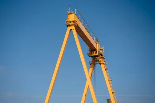
Across four decision criteria, the two arrangements line up as follows. (1) Maximum height: free-standing tops out at the manufacturer's rated free-standing height (commonly in the 30-45 m band for mid-size hammerheads and flat-tops); tied-in extends that limit to the building's full height because each new tie-in restores lateral restraint [S1][S2]. (2) Foundation cost: free-standing demands a large, heavily reinforced concrete pad sized for the full overturning moment, while tied-in spreads those reactions into the host structure and can use a smaller pad if the first tie-in is set early [S3][S5]. (3) Wind behaviour: both must satisfy the ASME B30.3 design wind case of about 45 mph (20 m/s) gust in service and a free-rotation out-of-service condition before shutdown, but the tied-in crane has additional real bracing from the collars, so it is more tolerant of the higher wind regimes found at the top of tall buildings [S5]. (4) Site disruption: a self-climbing tied-in crane is jacked in place, eliminating the need for a large assist crane on the roof for each mast addition, which matters on tight urban sites where street closures are costly [S2][S5].
The decision rule most planners apply is straightforward: if the finished top-of-structure is below the crane's rated free-standing height for the chosen jib length, a free-standing unit on a foundation is the lower-cost answer; if the building exceeds that limit, plan a tie-in or self-climbing configuration from the start, because converting a free-standing crane to a climbing crane mid-project is typically more expensive than the difference in rental cost up front [S1][S5].
Selection Criteria: What Drives the Choice on a Real Project
Three project inputs determine the support arrangement more than any spec sheet: building height, available base footprint, and surrounding airspace. Building height is the primary input because every crane model publishes a maximum free-standing height for each jib configuration, and exceeding that height without tie-ins is the single most common specification error found in peer reviews [S1][S5]. A second input is the foundation footprint, which on constrained urban sites can force a tied-in or internal-climbing solution even when the building is short, simply because the required pad will not fit inside the property line [S2][S3]. The third input is the surrounding airspace, since luffing-jib and flat-top cranes were developed for exactly the kind of overlapping-airspace jobs where a horizontal hammerhead jib would over-swing into a neighbor's rights-of-way [S2].
A fourth, often overlooked input is the wind regime at the site. The ASME B30.3 design envelope of about 45 mph (20 m/s) in service is a baseline; coastal sites, valley sites, or high-rise tops can see design gusts well above that, and a tied-in crane with intermediate collars will generally tolerate those higher gusts at full height better than a free-standing crane with extended mast [S5]. Engineers also size critical fasteners to 10.9 or 12.9 alloy bolt grades with traceable certificates, because a missed torque check at a tie-in collar has a much higher consequence than the same miss at a base anchor [S5].
Use Cases and Failure Modes

Free-standing tower cranes are the common answer for low- to mid-rise residential, commercial, and light-industrial jobs where the rated free-standing height covers the build and where the site can absorb a foundation pad; tied-in or self-climbing cranes dominate high-rise cores above roughly 12-15 stories where the building must lift materials faster than ground-level reach allows [S1][S4]. Within the tied-in family, self-climbing frames are preferred on tight urban infill jobs because they avoid the repeated use of a rooftop assist crane that a static mast-extension sequence would otherwise require [S5].
The dominant failure mode for free-standing units is over-height operation, where a crew climbs the mast past the rated free-standing height without first engaging tie-ins, producing an overturning moment that exceeds the base ballast and foundation reaction; the dominant failure mode for tied-in units is missed torque or missed weld inspection at the climbing collar, which leaves a single tie-in as the only restraint over a much larger column of mast and jib than it was designed to hold [S5]. ASME B30.3 addresses the second risk by mandating a major inspection every 60 months, which may include dismantling slew rings and non-destructive testing of key welds, with load-moment indicators, anti-collision zoning, and anemometer-driven shutdowns in place for in-service protection [S5].
Standards, Sourcing, and Traceable Signals
Both support arrangements are governed by ASME B30.3 (the U.S. construction and permanently mounted tower crane standard) and by ISO 4301-3:2021, which classifies tower cranes by load spectrum, cycles, and duty class and feeds those parameters into slew-bearing, hoist, and wire-rope sizing [S1][S5]. Manufacturer capacity charts, which always govern in the field, reflect three independent design limits: structural (mast and jib stresses), stability (slew-ring moment), and mechanical (hoist or trolley motor torque), and an engineer comparing free-standing and tied-in options for the same project will see different numbers on each line as the support arrangement changes [S5].
Trackable signals for an engineer comparing the two arrangements on the next project are: the manufacturer's free-standing height chart for the specific jib length being considered, the foundation reaction list for both the free-standing and the first-tie-in condition, and the climbing-collar spacing on a tied-in or self-climbing configuration matched to the host building's floor-to-floor height. For a broader look at how lifting equipment decisions ripple through a high-rise build, the rebar specification guide at Grade 60 vs Grade 75 vs Grade 80 Rebar: Yield Strength, Specs, and Selection covers the steel grades that the mast lattice and tie-in collars rely on for predictable ductility, and the crane selection context in How a Stacker Crane Retrieves Pallets from a Storage Rack shows how sister lifting equipment is integrated into the same site logistics plan.
Component reference pages worth checking: tower crane, signal tower light, and crane scale.