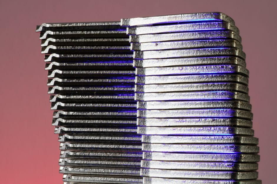
A proton-exchange-membrane (PEM) fuel cell stack is a serialized build of membrane electrode assemblies (MEAs) interleaved with bipolar plates, sealed and compressed into a rigid module whose electrical, hydraulic and thermal behaviour is captured by four coupled submodels — stack voltage, anode flow, cathode flow, and membrane hydration — at a uniform ~80°C operating point [S1]. The same source ties the voltage model to stack current, cathode pressure, reactant partial pressures, cell temperature and membrane humidity, and frames water transport across the membrane as the dominant dynamic that the build must physically sustain [S1].
From a process-engineering view, "stack manufacturing" therefore spans three distinguishable work-stages: MEA fabrication (catalyst-coated membrane, gas-diffusion layers, gasket frame), bipolar-plate and BOP preparation, and the final stack build (cell-by-cell stacking, tie-rod/compression, leak and electrical acceptance) followed by system-level test on a hydrogen-capable bench. FEV publishes a service envelope that mirrors this split, offering system development, build, vehicle integration, commissioning, calibration and testing of complete fuel cell systems, and disclosing five dedicated test benches rated up to 200 kW with environmental chambers spanning -40°C to +120°C and 10-98% RH [S2].
MEA sub-models: catalyst layer, ionomer film and agglomerate geometry
The OpenFCST project's SphericalAgglomerateGeometry class implements methods for calculating geometric parameters of a spherical agglomerate surrounded by a thin ionomer film, including functions to compute the agglomerate thin-film thickness based on the radius and structure, and to compute the volume fraction of nafion inside the agglomerate given the catalyst layer ionomer volume fraction, agglomerate size, and porosity inside the agglomerate [S3]. This thin ionomer film is the only proton-conducting path between the agglomerate surface and the surrounding void, which is why MEA coating uniformity — typically expressed in mg Pt/cm² and ionomer-to-carbon ratio — is the first yield gate in stack manufacturing rather than a downstream concern [S3].
For a process engineer the MEA line therefore needs (a) a clean-room coating step (slot-die, decal transfer, or spray) with sub-mg/cm² Pt-loading control, (b) a hot-press or roll-bond lamination for gas-diffusion-layer attachment with < 5% defect density, and (c) a frame/gasket cut-and-place step whose positional tolerance is set by the active-area seal-land width rather than by cell pitch [S3].
Stack voltage model and what it sets for build tolerances
The stack voltage submodel calculates output as a function of stack current, cathode pressure, reactant partial pressures, fuel cell temperature and membrane humidity, with the open-circuit voltage derived from the Gibbs free energy change ΔGf of the H2 + ½O2 → H2O reaction and three dominant loss terms (activation, ohmic, concentration) layered on top [S1]. The fast dynamic of the electrode RC network is described but is intentionally left out of the live model because its time constant is short relative to the other dynamics, which is why stack-build QA focuses on slow-loop behaviour: pressure-drop uniformity, humidification balance, and steady-state polarization curve shape rather than transient electrical response [S1].
Concretely, the voltage model fixes three manufacturing-relevant tolerances: cell-to-cell contact resistance (drives bipolar-plate surface finish and clamping force windows), membrane humidification uniformity (drives inlet RH set-point range on the test bench and the BOP humidifier spec), and gas cross-leakage rate (drives gasket compression set and seal-land flatness). The Springer source's 80°C isothermal assumption means the build must deliver a thermal path (cooling plates, manifold design) that holds every cell within a narrow band around that set-point under load, or the modelled voltage ceases to represent the as-built hardware [S1].
System-level test envelope: 200 kW, -40°C to +120°C, 10-98% RH
FEV's published test infrastructure — five dedicated benches, 200 kW maximum system power, -40°C to +120°C ambient swing, 10-98% relative humidity window, and on-bench gas-mixing for tailored hydrogen qualities — defines the de-facto acceptance envelope a stack must clear before it can be considered SOP-ready [S2]. The -40°C lower bound is the cold-start qualification point (PEM stacks must produce useful power from a frozen-soak condition), while the +120°C upper bound exercises the radiator-end and under-hood thermal derating case; 10-98% RH brackets both bone-dry cathode operation (dehydration stress) and condensing-humidifier operation (flooding stress) [S2].
Two practical consequences for the manufacturing line: first, every cell coming off the stacking station must be leak-tested at a delta-P that is a multiple of the maximum stack pressure differential seen on the test bench, because the bench will sweep the full RH range and any latent seal defect will present as a crossover leak under wet conditions. Second, the test cell's large-scale hydrogen infrastructure is what makes continuous operation of "systems of all sizes" economically viable, so stack throughput planning must be sized to bench availability, not to line cycle time [S2].
Submodel coupling and where the assembly line actually breaks
Where the four submodels meet is where stacks fail in the field: the membrane hydration model closes the loop between the cathode and anode flow models by representing water transfer across the membrane, and any build variation that breaks this loop — pinched flow channels, non-uniform GDL compression, plate-to-plate pitch error — shows up as a hydration imbalance that the voltage model then reads as a polarization-curve deviation [S1]. This is the engineering reason stack-level EOL testing is non-negotiable even when every individual MEA and plate passed its own in-process check.
A useful internal analogy: building a fuel cell stack is closer to battery pack cell-to-pack assembly than to discrete-parts assembly, because the product is a serialized repeating unit whose end-of-line behaviour is dominated by inter-cell uniformity rather than by any single component. The same discipline — positional tolerance of the repeating unit, compression control, and a polarization-style end-of-line test — appears in both domains, and the smart-manufacturing line architecture used in adjacent electrochemical cell plants transfers directly to MEA coating, plate cleaning, and stack compression stations.
Decision criteria: in-house build vs. system-integrator SOP
For an OEM evaluating whether to stand up a stack line or buy a system, four criteria dominate: power class (subcompact passenger car stacks are typically in the tens-of-kW range while commercial-truck and rail stacks reach the 200 kW class that FEV's bench envelope is sized for), cold-start requirement (the -40°C floor in the test envelope is a hard qualifier for most on-road applications), fuel-quality tolerance (FEV's on-bench gas-mixing capability exists precisely because real-world hydrogen quality varies), and control-software maturity (FEV's fuel cell system plant model library, maintained since 2000, is the kind of asset that an integrator brings to SOP and a first-time stack builder does not) [S2].
The trade-off is sharply asymmetric at low volume: an integrator path buys you a tested control strategy, a 200 kW-capable test bench, and supplier access, at the cost of per-unit margin and limited stack-IP capture; an in-house path buys you stack IP and unit-cost control, at the cost of replicating a five-bench test facility, a -40°C to +120°C environmental chamber set, and a control-software team that takes a decade to mature [S2]. The decision is therefore not technical-feasibility — the four-submodel stack architecture is published and well understood [S1] — but capital allocation against a forecast SOP volume.
Standards, sourcing and supplier-tier signals
Two sourcing signals are worth tracking in 2026. First, the QA stack for adjacent electrochemical products is converging on polarization-curve-based EOL acceptance with environmental-chamber qualification across the same temperature and RH bands that FEV publishes (-40°C to +120°C, 10-98% RH) [S2], so suppliers who already hold that envelope for lithium-ion pack testing are the lowest-risk entry point for fuel cell stack QA. Second, raw-material sourcing for the MEA catalyst layer (Pt-group metals) and the bipolar plate (coated stainless or composite) follows the same metallurgical spec-stack and supplier-audit pattern used in adjacent battery raw-material chains.
Trackable next nodes: a vendor's published MEA Pt-loading tolerance and ionomer-to-carbon ratio window (analogous to cathode-precursor spec bands in cobalt and nickel cathode-precursor lines), and a contract manufacturer's disclosed stack-test capacity in kW and chambers count — both are the leading indicators of who will reach fuel cell SOP in 2026 on a defensible process window rather than on a lab demonstration.
For component-level specifications, see additive manufacturing material, oxy fuel cutter, and load cell.