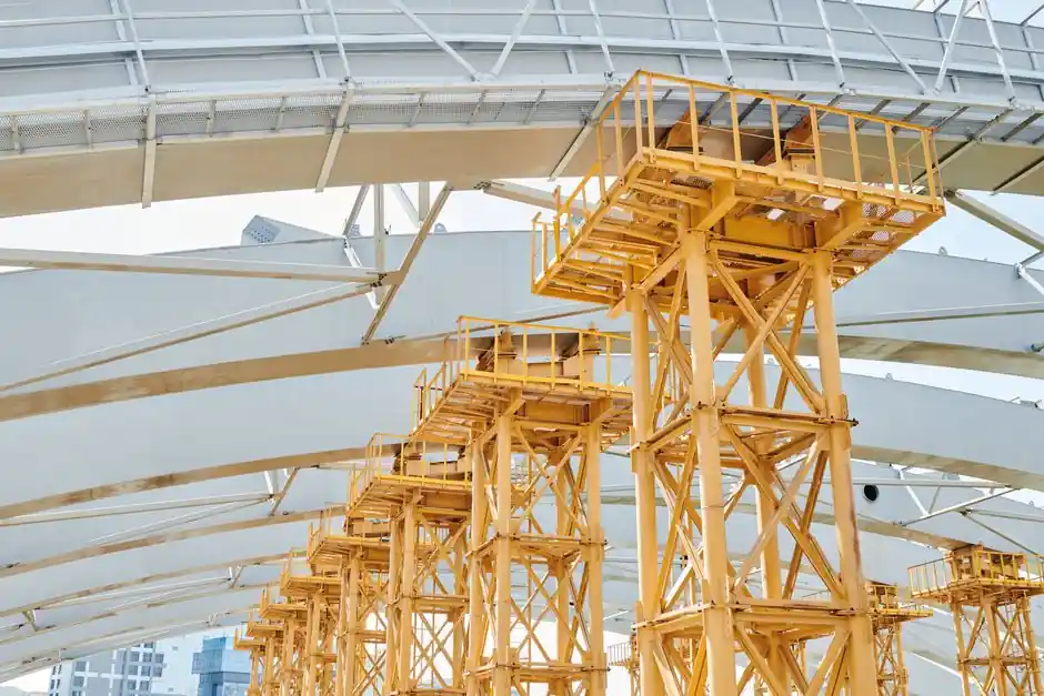
Flange parallelism is the single cross-sectional feature that separates an H-beam from a classic I-beam in practice: H-beams carry parallel inner and outer flange faces of essentially uniform thickness, while I-beams keep a tapered flange whose inner face slopes from the web junction out to the flange tip [S1][S2][S3].
The naming is visual, not a strict AISC designation: AISC "S" shapes and many standard "I-beams" are tapered, whereas AISC "W" (wide-flange) shapes and "HP" bearing piles fall into the parallel-flange H-beam family, and the same letter is used loosely across regions [S2][S3]. For this comparison the engineering question is narrower: what does a parallel flange change for bolting, weak-axis bending, and section selection on a real project?
Cross-section geometry: taper ratio, web-flange transition, and how it is measured
An I-beam flange is thickest at the web-flange junction and thinnest at the tip, with an inner-face slope of roughly 1:6 to 1:10 on common rolled profiles; the same profile shows a fillet radius at the transition, which is what gives the standard beam its "I" silhouette [S3][S4]. An H-beam (or wide-flange / W-shape) is rolled so that the inner and outer flange faces stay parallel within mill tolerance, the flange thickness is uniform from web to tip, and the web-to-flange transition is a sharper square corner with a small fillet rather than a long ramp [S1][S3][S6].
The practical difference shows up as soon as you put a straightedge on the flange: on an I-beam you can feel the slope; on an H-beam the straightedge sits flat along the inner face for the full flange width. Kloeckner Metals notes the four inner corners of an S-shape are sloped, while a W-shape stays blocky with uniform thickness [S3]; Delta Steel and Yena Engineering both call out the parallel-face flange plus thicker web as the defining H-beam geometry [S5][S6].
Flange parallelism vs. connection fit: bolts, welds, and clip angles
Parallel flanges change how a beam lands on its connections, and that is the most common reason a fabricator or erector switches profile mid-project. Because the H-beam flange face is flat from web to tip, a standard clip angle, end plate, or bolted flange plate sits in full bearing across the full flange width without shimming; with a tapered I-beam flange, the same plate only bears near the toe unless the connection is milled, shimmed, or detailed to follow the slope [S1][S3][S4].
The same geometry drives welding: a parallel flange accepts a uniform fillet weld leg length along the flange edge, while a tapered flange produces an inconsistent weld throat unless the fitter compensates with a variable gap. Mechanical Elements summarises the trade directly: tapered I-beams support flange-point loading better because the thick web junction plus radius spreads stress from a trolley or hoist wheel, while parallel H-beams are easier to bolt up because there is no slope to deal with at the connection [S4]. For column bases and moment-end-plate connections, the H-beam's flat face is what makes the standard AISC end-plate detail workable without tapered shim plates.
Structural behaviour: strong-axis bending, weak-axis stiffness, and buckling
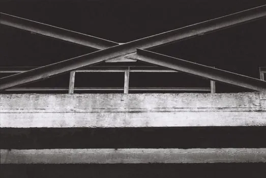
For strong-axis bending, depth drives section modulus far more than flange taper, so a deep I-beam and a deep W-shape of the same depth can carry very similar strong-axis moments once verified [S2]. The real divergence is on the weak axis: a wider, parallel flange pushes more area out to the flange tips, raising the weak-axis moment of inertia and radius of gyration, which directly improves weak-axis bending resistance, lateral-torsional buckling capacity, and column behaviour under bi-axial loading [S2][S5]. That is why H-beams and HP-piles are the common column choice, while I-beams stay in beam roles where strong-axis bending dominates [S2][S3].
Web thickness follows the same logic: H-beams are rolled with a thicker web relative to depth, which lifts shear capacity, web bearing capacity under concentrated loads, and local web buckling resistance, at the cost of extra steel weight for the same depth [S2][S5]. Yena Engineering quantifies the trade as "for the same structural support, you can use fewer H-beams than I-beams," but pays for it in raw kilogrammes per metre; SDC Verifier's comparison table makes the same point, noting that an H-beam of similar depth is typically heavier, and that weight is not free [S2][S5].
Selection criteria: when parallel flanges earn their premium
Specify an H-beam (W-shape or HP-pile) when the design is column-dominated, when bi-axial bending or strong weak-axis demand controls, when a moment-end-plate or bolted flange connection must bear flat across the full flange width, or when the member acts as a pile or heavy transfer girder with high axial load [S2][S3]. The parallel-face geometry also helps when the beam is erected against a precast slab or steel deck that needs a true 90-degree bearing surface along the flange edge.
Specify a classic I-beam (S-shape or standard "I") when strong-axis bending efficiency is the main requirement, when the member is a rafter, floor beam, gantry runway, or trailer frame where flange-point loading from wheels or trolleys benefits from the thick web junction and fillet radius, or when minimum self-weight per metre is the controlling cost [S3][S4]. As a working rule, a structural verification (not the section name) decides acceptability, so the I-beam must still pass the same bending, shear, deflection, lateral-torsional buckling, and connection checks under AISC 360 or the equivalent Eurocode 3 / GB 50017 envelope [S2].
Common mistakes when comparing the two on paper
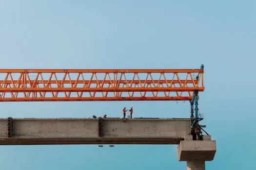
Treating "I" and "H" as exact engineering labels, rather than as visual nicknames, is the first trap, and it produces wrong section call-outs in procurement [S2][S3]. The second is assuming a heavier H-beam is automatically stronger: the extra mass sits in the web and flange width, so weight, depth, and grade all have to enter the comparison, not just kilogrammes per metre [S2]. A third trap is comparing a stock S-shape against a W-shape of the same depth and reading off only the strong-axis modulus, while the W-shape may have several times the weak-axis Ix and a much higher lateral-torsional buckling capacity for the same steel grade [S2]. Finally, never pair an I-beam with a connection detail drawn for a parallel flange, because the sloped inner face will leave the end plate rocking on the toe, and never assume flange parallelism on a generic "I-beam" without checking the mill certificate or the relevant AISC / EN 10034 / GB standard designation.
Standards, sourcing, and the next data point to track
Flange-parallelism tolerances are set by the rolling standard, not by the section name: AISC's steel-shape manual governs W, S, M, and HP designations in North America, EN 10034 covers European I- and H-sections, and GB/T 706 covers Chinese hot-rolled sections, with each standard specifying a maximum out-of-parallel across the flange face and a flange-thickness tolerance band that the mill certificate will report [S2][S3]. The next node to track on any H-beam vs I-beam decision is the verified section property table for the candidate profile, not the visual shape: pull Ix, Iy, Sx, Zx, rx, ry, and the flange slope ratio from the mill datasheet, run the same AISC 360 or Eurocode 3 check on each, and select the lighter verified section. For a deeper look at how parallel flanges interact with bolted moment connections, the wide-flange selection logic in our structural comparison guide walks through the same flange-bearing trade-off in ceiling-grid form, and a review of how flange geometry drives connection fit on heavy framing gives the matching mechanical-detail perspective.
Spec-level background on the components involved: flange, pressure transmitter, and flow meter.