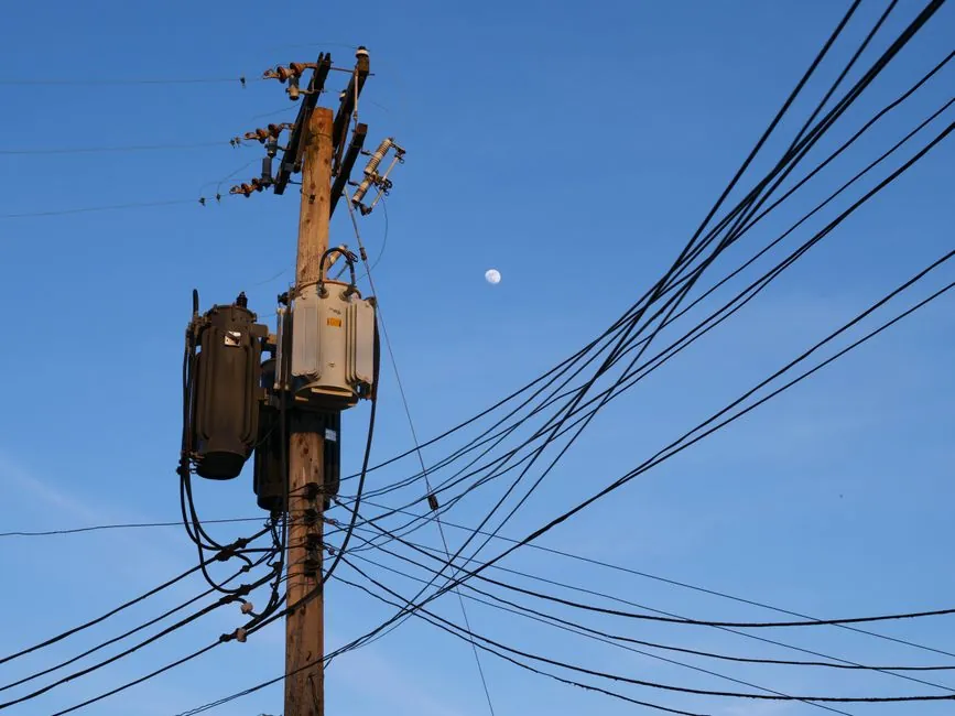
Harmonic filter sizing for industrial LV/MV systems is a measured-data exercise before it is a parts-ordering exercise: the 5th and 7th harmonic orders from 6-pulse VFDs and rectifier loads dominate, and detuned passive LC banks are typically tuned to 4.2, 4.7, or 6.7 to absorb those orders [S1].
The selection decision pivots on three inputs: a one-line diagram with source impedance, a measured THDi spectrum and individual harmonic current Ih per order, and the load profile (static vs dynamic) [S4][S6]. Quality factor Q for a single-tuned passive filter commonly lands in the 30-100 band, and capacitor kVAr is the design variable that locks in the inductor reactance once the tuning ratio is chosen [S1].
Detuned Passive vs Single-Tuned vs Active vs Hybrid: Which Topology Fits
Detuned passive LC banks are the workhorse for 5th-harmonic mitigation on six-pulse rectifier and VFD buses, and the industry default detune ratios sit at 4.2 or 4.7 for the 5th order and 6.7 for the 7th order rather than at exact integer tuning [S1]. Exact tuning is avoided because device tolerance and component degradation shift the resonance over time, and a tuning margin of 3-15% below the target harmonic is the IEEE-recommended starting band for filter design [S3].
Single-tuned (notch) filters, broadband high-pass filters, band-pass filters, and C-type filters are the four standard passive topologies covered in mainstream sizing packages, and they are chosen by harmonic spectrum width rather than by kVAr alone [S2][S3]. Active harmonic filters (AHF) inject an inverse-polarity current to cancel measured harmonics in real time, which makes them the right answer for dynamic, fluctuating non-linear loads where a passive bank would have to be oversized to cover the worst case [S5][S6]. Hybrid filters combine a passive LC section with an active stage, trading some of the dynamic correction of a full AHF for a lower price point on lightly variable loads [S5].
A simple decision matrix lines them up against four criteria that buyers actually score on:
Topology vs load variability: detuned passive and single-tuned notch filters fit static or slowly varying loads (PF-correction-style duty) [S1][S5]; broadband high-pass and C-type filters fit wide-spectrum harmonic sources like arc furnaces [S3]; active filters fit fast-changing VFD clusters, data-center UPS buses, and any load where the harmonic spectrum shifts minute to minute [S5][S6]; hybrid filters fill the gap where dynamic correction is wanted but full AHF cost is not justified [S5].
Sizing a Passive Filter: kVAr, Reactance, and Q-Factor
The sizing calculation on a passive filter starts with the capacitor bank reactive power Qc (Mvar) needed for PF correction or voltage support, then back-solves for capacitive reactance, inductive reactance at the chosen tuning order, characteristic reactance, and finally the damping resistance from the desired quality factor Q [S1]. Raising the Q factor (often 30-100) sharpens the notch and improves harmonic trapping at the design frequency, but lowers the filter bandwidth and increases voltage stress across the capacitor at harmonic order hn [S1][S3].
There is a direct kVAr-vs-reactor trade-off in this design: if the capacitor kVAr is pushed to its minimum, the harmonic filter reactor size grows, and vice versa, so the engineer has to compromise between the two when sizing a shunt passive filter [S1]. The effective filter Mvar at the tuned frequency, the voltage across the capacitor, and the filter quality factor Q (30-100 typical) are the three outputs that confirm the design is workable, and they should all be checked before the bank is ordered [S1].
Detuning below the target harmonic (the 3-15% margin) is a safety move: it accounts for natural system variations such as loss of transformers, equipment replacement, routine maintenance, manufacturer tolerances in both reactors and capacitors, capacitance drift with temperature, and capacitor unit/element failure from fuse operation, all of which push the resonant frequency upward over service life [S3].
Sizing an Active Filter: Compensation Current and THDi Targets
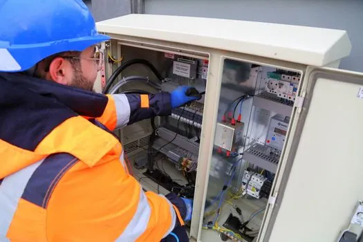
Active harmonic filter sizing is data-driven, requiring comprehensive information such as a harmonic analysis and a target THDi limit, with a common THDi threshold of 5 percent or so typically necessitating harmonic mitigation [S4][S5][S6].
Sizing an active harmonic filter involves measuring harmonic current (Ih) and assessing Total Harmonic Distortion, conducting a comprehensive harmonic analysis, and calculating the compensation current required [S6][S8]. Selection of the right compensation current rating (commonly 50 A, 100 A, 200 A, 300 A modules paralleled for higher ratings) is then matched to the PCC short-circuit ratio and the total non-linear load share [S6].
Two preconditions gate AHF deployment: the filter must be installed at a bus where the harmonic distortion is actually measurable above the compliance threshold, and the load profile must justify the dynamic-response premium of an active topology over a passive bank [S5][S6]. Sizing tools from vendors such as Powerside (PowerAct), ETAP, TCI, and Ampersure all take the same baseline inputs (one-line, load list, spectrum, THDi target) and output a recommended compensation current and module count [S2][S7][S8][S9].
VFD-Duty Selection: Thresholds, Mistakes, and Filter Mapping
For variable frequency drives, the standard trigger for adding any harmonic mitigation is a measured THDi above roughly 5% at the VFD input terminals, with common precursor symptoms being equipment overheating, nuisance circuit-breaker tripping, and unexplained energy loss [S5]. A line reactor alone is the lowest-cost first step and is appropriate where the goal is dV/dt protection and modest harmonic reduction rather than THDi compliance, while multi-pulse transformers and active front-end drives are the alternatives when the harmonic budget cannot be met with filtering alone [S5].
The filter-type mapping for VFD duty: passive detuned banks on shared bus feeders feeding multiple 6-pulse VFDs; active harmonic filters on dedicated VFD buses with frequent setpoint changes; hybrid filters where partial dynamic correction is acceptable and capital cost is constrained; line reactors as a baseline dV/dt and surge protection device, not a stand-alone THDi solution [S5]. Common sizing mistakes on VFD duty include undersizing for peak load (using average kVA rather than peak harmonic current), ignoring background voltage distortion at the PCC, and treating a line reactor as equivalent to a harmonic filter [S5][S6].
For a clean spec-driven shortlist, four filter types cover the bulk of VFD and industrial-rectifier duty: passive detuned (5th/7th), passive broadband high-pass (wide-spectrum), active harmonic filter (dynamic, multi-order), and hybrid (cost-optimized partial dynamic). Compare on Q-factor/selectivity for passive types, on compensation current rating and response time for active types, and on total installed cost per ampere of harmonic current mitigated across all four [S2][S5].
Who Should Not Pick the Default: Limits and Failure Modes
Passive detuned filters are the wrong default on three specific duty profiles: heavily fluctuating loads where the harmonic spectrum changes faster than the filter can be re-tuned, weak grids with high source impedance where the filter interacts with the system and can shift the parallel resonant frequency toward an existing harmonic, and applications where fundamental-frequency reactive power is not wanted (the filter looks capacitive at 50/60 Hz) [S3][S5].
Active filters fail when the harmonic content is dominated by a single order with very high magnitude, when the PCC is too stiff and the filter cannot push enough compensation current into the network, or when the load is essentially linear and the THDi is already below 5% [S4][S5]. Hybrid filters underperform when the passive stage is mis-sized to the dominant harmonic order, leaving the active stage to chase orders it cannot economically cover [S5].
Across all topologies, two failure modes recur in field service: capacitor-element failure from fuse operation, which raises the resonant frequency of the bank and shifts the trap upward, and reactor saturation under high harmonic current, which detunes the filter away from the design point [S3]. Both modes argue for built-in monitoring of filter status contacts and for re-commissioning after any capacitor or reactor replacement.
Standards, Sourcing Inputs, and a Shortlist Logic
The IEEE Guide for Application and Specification of Harmonic Filters defines the design-procedure backbone that ETAP, PSCAD, and vendor sizing tools implement: determine filter-bank kVAr size, select initial tuning 3-15% below the target harmonic, optimize filter configuration to meet harmonic guidelines such as IEEE 519, and verify performance across normal and contingency conditions [S2][S3]. For the typical buyer, the shortlist workflow is: (1) capture the one-line, the measured Ih spectrum, the THDi at the PCC, and the load profile [S4]; (2) match static loads to a detuned or single-tuned passive bank sized for kVAr and Q [S1][S3]; (3) match dynamic non-linear loads to an AHF sized for compensation current with a 20-30% margin [S6][S8]; (4) for cost-constrained mixed loads, evaluate a hybrid topology [S5]; (5) verify the chosen filter against IEEE 519 voltage and current distortion limits at the PCC before release [S2][S3].
Encyclopedia reference pages for related power-quality and motion-control components are available at the harmonic filter, harmonic reducer, and linear guide entries, and selection context for adjacent industrial subsystems is covered in the construction machinery and equipment and lamps and light fittings reference pages.
Trackable next signals: monitor the IEEE 519 compliance threshold revision cycle and vendor AHF module-current ratings (50/100/200/300 A tiers) for the next 12 months, since both directly determine whether a passive bank or an active bank is the more economical shortlist pick on a given bus.
Related analysis: Steel Mill Gear Coupling Selection: Shock, Series, and Sizing Map.