
A liquid silicone rubber (LSR) injection mold is the thermal mirror image of a thermoplastic mold: the barrel stays cool, the cavity plate is held at 160-200°C, and the heat that cures the part is delivered almost entirely through a heated mold base rather than the melt itself [S2].
That single inversion, cool barrel / hot tool, drives every downstream decision on steel grade, channel layout, gate geometry, and draft; the A2 precision closure tolerance of ±0.20 mm at 0-10 mm features is the only realistic target a designer can hand to a molder and expect repeatable medical or food-grade LSR parts [S4].
Why LSR Needs a Heated, Not Cooled, Mold Base
LSR is a two-part platinum-cured thermoset: a metered A/B mix is injected into a sealed, heated cavity where vulcanization happens by chemical cross-linking, not by solidification of a melt, and once cross-linked the polymer cannot be remelted [S1][S2]. The meter/mix unit feeds a spring-loaded (or positively shut) nozzle that prevents back-flow into the screw, and the heated cavity initiates cure from the steel surface inward, so the mold base is a process reactor, not just a forming tool [S1][S3].
That is why silicone rubber LIM is treated as a fundamentally different workflow from HCR (high-consistency rubber) strip-fed molding: the runner system is cold while the cavity is hot, and thermal separation between the runner plate and the cavity plate is a primary design constraint, not a refinement [S2]. Rubber is a poor thermal conductor, so thick LSR sections need a longer hold at 170-190°C to cure the core before ejection, while thin flash-prone sections need tight thermal symmetry to avoid over-cure at the parting line [S2][S6].
Steel Selection, Surface Finish, and Cavity Machining
Pre-hardened tool steel (P20 / 1.2738 class) is the default for LSR cavity and core inserts in medium-volume production because it ships at 30-34 HRC, machines cleanly, and polishes to the 32-64 microinch finish that allows LSR to release without mold spray or release agent [S4][S7].
For high-cavitation medical tooling or inserts with shut-off features, H13 (≈50 HRC) or S7 is often specified, but the trade-off is machinability and weld repair cost, so most commercial LSR tooling stays in the P20 / 420 stainless band, with 420 stainless preferred for cleanroom and food-contact parts because it does not rust in heated, humid idle states [S7]. The 32-64 microinch (Ra ≈ 0.8-1.6 µm) cavity finish is the published industry default; smoother finishes (SPI-A1/A2, Ra 0.05-0.2 µm) are used only where optical clarity or ultra-low-tack surfaces are needed, since LSR sticks tenaciously to highly polished steel until it is fully cured [S4].
Heater Cartridge Layout and Cooling Channel Strategy

Cartridge heaters (typically ½" or ¾" diameter, 100-250 W/in² density) are pressed into bores in the cavity retainer and core plate, with one heater per 80-120 cm² of cavity area as a starting rule, then tuned by thermocouple survey to hold ±3°C across the cavity footprint [S2][S6].
Cooling channels in an LSR tool are not the primary thermal control, they exist to protect the runner system, slides, and ejector housing from the 160-200°C cavity heat, and they are normally placed 12-20 mm below the cavity surface in the cavity retainer and 15-25 mm below the parting line in the core half [S2]. A common design rule is to keep heater-to-channel distance ≥ 1.5× the channel-to-cavity distance, otherwise the channels steal too much energy from the heaters and cycle time grows by 10-20% on production runs [S2]. For multi-cavity LSR molds, a heated manifold block with one thermocouple per cavity is preferred over parallel daisy-chained heaters, because the ±5°C drift seen on series circuits routinely produces one over-cured and one under-cured cavity in the same shot [S6][S7].
Draft, Undercuts, and the Case for Zero-Draft Parts
LSR's high tear strength and low modulus after full cure (typically Shore A 20-70) allow molded components to be stripped from undercuts and even from zero-draft steel surfaces without distortion, which is a structural difference from thermoplastics where 0.5-1.0° draft is mandatory [S4][S7].
That property lets designers collapse ejector pins, slides, and lifters in many LIM parts, and Stockwell's published design guidance specifically notes that uncured LSR at injection viscosity (typically 100-1,000 Pa·s) will flow into any void larger than 0.0005" (≈ 0.013 mm), so ejector pin bores and slide clearances must be sealed or they will flash and clog within a few shots [S4]. The practical rule is: use zero draft where geometry allows and the part is a simple seal or gasket; introduce 0.25-0.5° draft only on long, thin walls and on textured surfaces where knit-line release force is high [S4][S7].
Gate, Runner, and Parting-Line Design for Heated Cavities
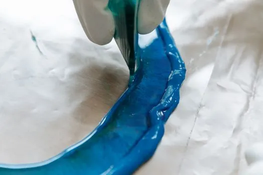
Gating in LSR molds is almost always at the parting line, with cold-runner or cold-deck systems feeding a heated cavity, and a 2-plate mold is the default because it keeps the runner cold and the cavity hot in two cleanly separated plates [S4]. Submarine gates, tunnel gates, and pin gates are all usable, but pin gates below 0.5 mm diameter are discouraged on fiber-filled or self-lubricating LSR grades because the cured material wedges in the gate and stops the next shot [S2][S4].
Parting line flash on LSR is the most common defect and is driven by thermal expansion of the cavity at 180°C, which grows a 100 mm steel plate by roughly 0.12 mm, so the closed-mold clamp force (typically 200-400 kN for a small LSR press) must overcome both injection pressure (5-15 MPa for LIM) and thermal growth of the parting surface [S2][S6]. Cryogenic de-flashing with liquid nitrogen tumble is the standard secondary operation for medical and food-grade parts, and a properly designed mold can keep flash under 0.05 mm so de-flashing becomes a 5-10 second pass rather than a 30-60 second rework [S4][S6].
Comparing Mold-Base Options for LSR Production
For engineering buyers choosing between tooling classes, the three dominant options line up against cost, lead time, and tolerance: a single-cavity prototype mold (P20 steel, polished, cartridge heated) at 6-10 week lead time and roughly $8-15k tooling cost; a 4-16 cavity production mold (P20 or H13, hot-runner capable, individual cavity thermocouples) at 10-14 week lead time and $25-80k; and a high-cavitation medical mold (420 stainless, 32+ cavities, full cleanroom validation) at 16-24 week lead time and $150k+ [S4][S6][S7].
On the four decision criteria that matter for an LSR program, draft flexibility, cavity surface finish, thermal symmetry, and dimensional closure tolerance, the single-cavity prototype scores well on draft and lead time but poorly on ±3°C cavity symmetry across a 200 mm footprint, while the multi-cavity production mold hits ±0.013 mm closure tolerance at 16-25 mm features (per A2 precision) only when each cavity has its own heater zone and thermocouple [S4]. A useful engineer-to-engineer benchmark: if the part wall section varies by more than 3:1 across the cavity, drop to a single-cavity prototype first, because variable wall thickness in a heated mold produces over-cured thin sections and under-cured thick sections in the same shot, and the A2 tolerance table does not save you from a chemistry problem [S2][S4].
Defects, Limits, and Operator-Lever Settings
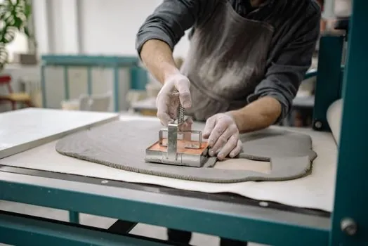
The three failure modes that show up in production LSR molds are parting-line flash (almost always clamp force or thermal-growth related), incomplete cure in thick sections (cure time or heater temperature set too low), and ejector sticking (cured LSR in a clearance, which the 0.0005" flow rule predicts precisely) [S2][S3][S4].
Operator-lever settings that move the process window the most are injection pressure (5-15 MPa for most LSR grades), cure time (typically 30-90 s at 180°C for 2-4 mm wall), and mold temperature (each 10°C reduction below 170°C roughly doubles cure time, and each 10°C above 200°C risks mold fouling and degradation of the platinum catalyst residue) [S2][S3][S7]. The reference signal a process engineer should track on every shot is the cavity thermocouple trace: a flat-top profile at ±2°C of setpoint through the hold phase is the single best indicator that the heated mold base is performing as designed, and any downward drift of more than 5°C between cycles points to a failing cartridge heater or a water-cooled channel that has migrated too close to the cavity [S2][S6].
Trackable next node: confirm whether your tooling shop machines to 32-64 microinch (Ra 0.8-1.6 µm) as a default or specifies it in writing, because unstated finish expectations on silicone rubber LIM tooling are the most common source of flash and release-agent disputes on the first 50 shots.
Component reference pages worth checking: casting mold.
This topic is covered further in POM Homopolymer vs Copolymer: Gear Selection Guide.