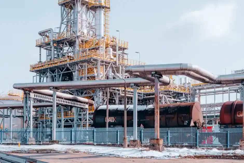
Amine delivery to a steam/condensate system splits into two physical routes: vaporization of a heated amine-water stream and flash-distribution with steam, or pumping a liquid amine stream directly into the steam header or feedwater line [S3].
The split is not academic. Vapor/liquid distribution ratios differ by orders of magnitude between morpholine, cyclohexylamine, diethylaminoethanol, and ethanolamine, and the same amine can swing from volatile to non-volatile depending on whether CO2 is present in the steam [S3]. That single ratio decides whether the chemical will reach the condensate return or deposit in the boiler.
V/L Distribution Ratio and Where the Amine Ends Up
Neutralizing amines are dosed to keep condensate pH in the 7.5-9.0 band so that carbonic acid from dissolved CO2 does not chew through carbon-steel returns [S3]. The mechanism only works if the amine actually rides with the steam. Morpholine has a relative V/L ratio high enough to follow steam into the condensate, while heavier amines like cyclohexylamine tend to partition into the liquid phase and recirculate with the condensate [S3].
Practically, this means a heated amine vapor generator is the natural fit when the goal is to protect a long, dry steam header and the first condensate leg, where any acid would attack the metal before a liquid buffer can form. Liquid amine injection, often via a metering pump at the deaerator or feedwater line, targets the bulk feedwater chemistry and the boiler internals rather than the vapor path. The decision is dictated by where the corrosion threat is highest, not by equipment cost [S3].
Fouling Behavior at Boiler Tube Temperatures
The "volatility advantage" of vaporized amines is reversed once the chemistry hits a heat-transfer surface. Morpholine (MPH) and ethanolamine (ETA) have been measured as fouling enhancers compared with amine-free water at the same high-temperature pH [S2]. In other words, the same amine that protects the condensate can bake onto the fire-side or steam-side tube wall once it condenses on a hot surface.
For operators, this is the central tradeoff in the [heated amine vapor generator vs liquid amine injection] debate. Vapor feed means more amine reaches the steam tubes, and a higher fraction of that amine can decompose into acidic byproducts or polymerize on the heat-transfer surface. Liquid injection into the feedwater delivers the amine in a more controlled way, but the amine still flashes with the boiler water, and any overfeed pushes the same fouling mechanism. Specifying a low-fouling blend, keeping feedwater amine residual below roughly 1-2 ppm total, and monitoring condensate conductivity are the three levers that consistently keep the fouling tendency in check [S2].
Layout, Equipment, and Integration Effort
A heated amine vapor generator is essentially a small kettle reboiler or steam-heated evaporator that flashes the amine-water blend into a low-pressure vapor line, mixed with a carrier steam slipstream, before injection into the main steam header. Skid size is dominated by the heat-exchanger area needed to vaporize the dilute amine solution, and a vacuum pump or eductor is sometimes fitted to keep the vaporizer below 100 °C when heat-sensitive amines are used [S1].
Liquid amine injection, by contrast, is a chemical-feed skid: a storage tank, a metering pump (typically 0-100 percent stroke with 4-20 mA control, paired with a stroke-frequency or flow meter feedback), and a quill or injection nozzle in the feedwater line. A single pressure transmitter on the injection line and a static var generator on the pump VFD are often added where plant power quality is poor. The mechanical envelope is roughly 10-20 percent of a vaporizer skid of equivalent throughput, and the controls are simpler because the heat-balance loop is absent [S4].
Comparison Matrix: Decision Criteria Side by Side
For an engineer writing a spec, the four criteria that matter most are listed below, with the typical direction of preference:
1. pH control band achieved in the condensate. Vapor feed holds pH 7.5-9.0 more uniformly on long headers because the amine rides the steam directly [S3]. Liquid injection can leave the first condensate leg acidic if feedwater residence time is too long.
2. Fouling risk on heat-transfer surfaces. Vapor feed carries more amine into the boiler; morpholine and ethanolamine are documented fouling enhancers above 200 °C tube-metal temperature [S2]. Liquid injection to feedwater carries a similar but typically lower load, because the amine concentrates in the boiler water rather than on the tube wall.
3. Capex and footprint. Liquid injection is the low-capex default; vaporization adds a heat exchanger, a level-controlled amine tank, and a vacuum generator or steam coil that often doubles the skid cost.
4. Suitability for low-pressure steam. Vaporizers lose efficiency below roughly 3 bar(g) because the carrier-steam energy available to flash the amine drops. Liquid injection scales gracefully down to 0.5 bar(g) humidification lines [S3].
Where Each Option Fits and Where It Does Not
Heated amine vapor generation is the right call for medium-pressure header protection (5-20 bar(g)) on pharmaceutical and hospital clean-steam systems, where the absence of particulates and a tight pH window on long distribution loops are mandatory [S3]. It is the wrong call for a 0.5 bar(g) clean-steam loop serving a small humidification grid: the carrier-steam enthalpy is not enough to flash the amine-water blend, and the reboiler stalls.
Liquid amine injection is the right call for bulk power and industrial boilers, where the corrosion threat is dominated by feedwater and deaerator-side oxygen and CO2, and where amine residuals of a few ppm are tolerated in the boiler water. It is the wrong call for direct steam humidification of occupied indoor air, because the amine that flashes with the steam shows up in the room air, and OSHA, FDA, and NIOSH have published ceiling limits for cyclohexylamine, morpholine, and DEAE that an atmospheric release will breach within hours of overfeed [S3].
Limitations, Failure Modes, and Trackable Signals
The two dominant failure modes for either system are amine overfeed (condensate pH drifts above 9.0, leading to gassing and copper-alloy attack in the condensate return) and amine underfeed (condensate pH drops below 7.0, and the carbonic acid attack on the carbon-steel header begins within weeks). For vapor systems, a third failure mode is heat-exchanger fouling from amine degradation products, which shows up first as a rising approach temperature on the reboiler; a 5-8 °C drift over 6 months is a hard flag to pull the bundle [S2].
For liquid-injection skids, the most common failure is pump diaphragm wear, which manifests as a loss of stroke repeatability; tracking the flow meter feedback against the 4-20 mA setpoint and watching the deviation band over a 24-hour window is the cheapest predictive signal. The next node to track is the condensate conductivity and pH at the far end of the steam distribution loop, logged on a daily basis; a 5 percent week-on-week rise in conductivity at constant amine feed is the early warning that CO2 is breaking through and the amine chemistry is no longer keeping up [S3].
Background reading: Guided Twin-Rod vs Single-Rod Cylinders: Side-Load Decision Guide.