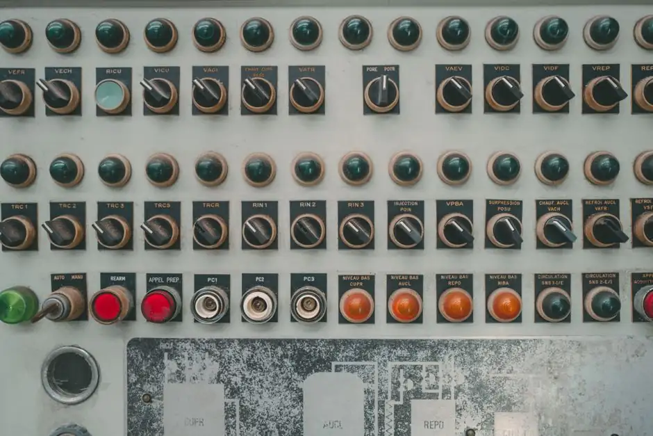
Horizontal gravity die casting (GDC) cells tie the die-close cylinder, the servo or hydraulic tilt axis, the pour-ladle and the guard door into one PLC-managed interlock chain, so no motion can start until every upstream sensor confirms a safe state [S3][S6].
Modern horizontal GDC platforms carry up to 4,000 kg mould weight, deliver tilt ranges of −20° to +110°, and reach full-sweep tilt cycle times of 60-150 sec depending on the size class [S3]. The interlock system is the only thing that keeps a 4-tonne permanent mould from closing on a misplaced sprue or rotating past its mechanical stops.
What the interlock chain actually controls
On a horizontal GDC cell the PLC orchestrates seven sequential states: guard-door closed and light curtain clear, mould heating zones at set-point, die-close cylinder in locked position, tilt axis at pour angle, pour-weight sensor armed, return-tilt complete, and ejector cylinder retracted [S3][S6]. The safety light curtain plus dual-handed start interlock is a standard feature across the FMU and FCL families, not an option [S3].
Interlocks are not optional sequencing, they are the only mechanism preventing molten aluminium (poured at 680-720°C in typical aluminium permanent-mould work) from spilling when the cell is partially guarded [S7]. The electrical control system of any die casting machine is defined as the function that "controls the execution of each mechanism of the die-casting machine to run according to a predetermined program", with parameter detection, fault alarm and process monitoring listed as advanced features on top [S2].
Servo tilt vs hydraulic tilt: feedback architecture differences
Servo-driven tilt axes on rotary GDC machines (Japan Yaskawa drives in the FMU/R series) deliver ±0.05° tilt accuracy and accept 20-40 programmable pour points, giving the PLC a digital position register to interlock against rather than just a limit-switch flag [S3]. The repeatability is what lets the controller hand off the pour trigger to a robot or auto-ladle with a millisecond-grade hand-shake, a pattern widely used in automotive cylinder-head and aluminium-wheel cells [S1][S3].
Hydraulic tilt cells (FMU1 and FMU2 series) use proportional valve control with a 5.5-11 kW hydraulic power pack and rely on inclinometer feedback plus mechanical end-stops; tilt cycle time on a full sweep runs 6-15 sec on the small frame and 10-15 sec on the 800 mm daylight size [S3]. The interlock chain still gates motion on door, mould-close and heating-zone confirmation, but the tilt position itself is an analog signal with wider tolerance, so the PLC is typically configured with a wider safe-position band before allowing pour-arm advance.
Mould-close and clamping interlocks

Clamping force is the primary parameter that sizes a die casting machine and is expressed in kN; small machines sit at ≤4,000 kN, medium at 4,000-10,000 kN and large at ≥10,000 kN [S2]. On a horizontal GDC cell the equivalent is the static clamping force of the die-close cylinder (120-350 kN on the FMU2 static gravity casting range) plus a position-confirmed closed switch before the tilt sequence can begin [S3].
For high-pressure die casting, the reference is a double multiple shear toggle clamping linkage that holds the mould against injection pressure, distributes load across steel pins in steel bushings, and reduces wear through multiple shear points; without a toggle or a two-platen with linkage, mould separation and flash are documented failure modes [S4]. GDC does not hit the same injection pressures as HPDC, but the same interlock principle applies: the PLC must read a positive die-closed signal (pressure-switch plus mechanical limit) before enabling tilt and pour [S2][S4].
Safety circuit and guarding
Every GDC cell in the FMU1/2/R and FCL ranges ships with a safety light curtain plus dual-handed start interlock as a standard feature, and the FCL-Twin and FCL-Island variants add a cell controller on top of the PLC and HMI to coordinate gantry-robot core insertion, auto-ladle pour and inspection stations [S3]. Output on the FCL-Island hits ~240 cylinder heads per shift, so a single nuisance-trip on the light curtain costs measurable tonnage.
Operator-level GDC reference material lists die casting machinery guarding under the same interlock umbrella as the machine functions themselves: a guarded cell has its door status, light-curtain status and emergency-stop chain all wired into the same safety relay that drops the tilt and clamp solenoids to a safe state [S6]. For related interlock logic on adjacent equipment, see the roller conveyor gate interlock wiring and standards article, which covers the same dual-channel safety-relay pattern on conveyor cells.
Process interlocks: heating, cooling, and metal supply
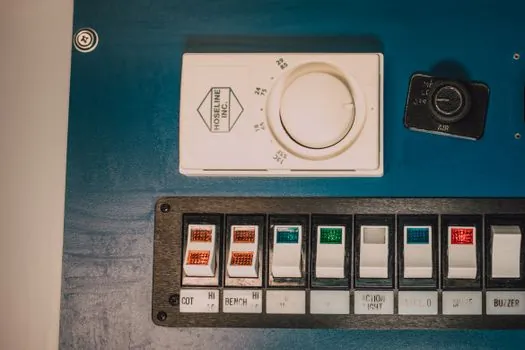
Mould heating is split into 3-4 zones (cope, drag, core) with separate control loops, and a multi-zone oil-based mould-temperature controller up to 350°C is offered as an option for tighter thermal interlock [S3]. The PLC will typically refuse to enable tilt and pour until all heating zones are within a configurable band of set-point, because pouring into a cold zone cracks the iron and pouring into an over-temperature zone accelerates soldering.
For the upstream metal supply side, the holding furnace must deliver metal within a narrow temperature window before the GDC pour sequence is even armed, a topic covered in the holding furnace temperature control for die casting metal supply reference. The pour-weight sensor on the FCL-Island is wired into the same interlock chain so an under-weight or over-weight pour aborts the cycle before tilt-return [S3].
Where horizontal GDC interlocks differ from high-pressure die casting
High-pressure die casting interlocks revolve around injection end-of-stroke, intensification pressure, and toggle-linkage lock confirmation, because the safety-critical event is mould separation under thousands of kN of injection force [S2][S4]. Horizontal GDC interlocks revolve around tilt angle, pour-weight, and guard-door state, because the safety-critical event is molten metal spill from a rotating mould or a prematurely opened guard [S1][S3][S5].
The tilting-pour process used for high-voltage switch tank bodies and conductor castings reports metal utilisation above 75%, productivity around 8 pieces/hour and casting yield above 95%, which means an unprotected GDC cell is a higher-frequency hazard than a single HPDC shot [S5]. A full background on GDC machinery functions, including how the pouring, spraying and picking auxiliaries are sequenced, is in the operator-level reference material at diecasttraining.net [S6], and the gravity die casting encyclopedia page covers the broader machine taxonomy. For a wider view of the die casting machine family, including hot-chamber and cold-chamber variants, the classification breakdown by clamping force (≤4,000 / 4,000-10,000 / ≥10,000 kN) is the standard reference [S2].
Trackable signals for the next planning cycle: any release notes from OMRON, Yaskawa or ABB that change the safety-relay or functional-safety firmware baseline on GDC controllers, and any update to the ISO 12100 / ISO 13849 risk-assessment expectations for permanent-mould cells. The die-cast training and Shibaura Machine toggle-linkage references remain the cleanest public engineering write-ups of the underlying interlock logic for the next quarter [S4][S6].
Component reference pages worth checking: aluminum die casting machine.