
On a powered roller conveyor, the gate interlock is wired into the motor's safety-enable circuit so that opening the gate removes the run permissive before a hand can reach a pinch point. Practical builds on conveyor lines ship at 24 VDC for motorized roller (MDR) zones, while heavier line-shaft and chain-driven live roller (CDLR) lines still run 480 V three-phase gear motors behind a contactor or VFD [S4].
The interlock itself is almost always a positive-break safety switch on the gate hinge or latch, returning a dry contact to the conveyor's safety relay or to the drive controller's enable input [S9]. On a roller conveyor with a single central drive, that dry contact is wired in series with the contactor coil; on a zoned MDR line, the same contact is mapped into the PLC that controls the individual 24 VDC roller cards, which is why the Turck TBEN block encapsulates both the CAN protocol for the rollers and the discrete safety I/O in one IP67 module [S1].
Three physical layers: power section, gate switch, and logic device
Every gate-interlock design stacks three hardware layers, and the failure mode of each is different. The power section is the drive itself, which on a 24 VDC MDR zone can be grabbed by a bare hand and stalled, while a 5 HP 480 V gear motor driving a chain-and-sprocket line-shaft conveyor is "a dangerous animal" if a person enters the drive train [S4]. For that reason the interlock must sit ahead of, not after, the energy source: the contactor or VFD STO input is upstream of the motor, and the gate switch is the thing that releases that upstream permit.
Industry practice places a positive-break safety interlock switch on the gate's hinged edge or latched position, then runs its two contacts through a Cat. 3 / PLd safety relay or a safety PLC. Lift-gate conveyor builders publish exactly that wiring: the interlock provides a dry contact signal that the conveyor is in the ready position, and the controller refuses to start, or coasts and drops the run permit, the moment that contact changes state [S9]. The same dry contact also feeds upstream permissives such as zero-pressure-accumulation release, so a single open gate halts the whole upstream zone train, not just the local motor.
Wiring topologies: contactor coil, VFD STO, and PLC enable
For a single-motor line-shaft or CDLR conveyor, the cheapest proven topology is a hardwired interlock in the contactor coil circuit, where the safety switch contacts are in series with the coil and an E-stop. This matches the patent US6409011B1 description of gate interlocks provided at the joint between gate and fixed sections to avoid a gap or pinch point [S8]. The drawback is that the gate also breaks production any time it is opened, even briefly, which is why most modern lines move the interlock into the drive controller instead of the main contactor.
For a VFD-driven live roller line, the gate switch feeds the drive's STO (safe torque off) input or a configurable safety function block. This is functionally equivalent to a contactor drop but lets the drive brake in a controlled ramp instead of coasting, which matters on inclined runs where a coasting load can drift back through the gate. The compact, modular variant for MDR uses a TBEN-style block that drops the 24 VDC bus to the roller cards while broadcasting the gate state to the rest of the network over CAN, as documented in the Turck flexible-drive-control note [S1]. In all three cases, opening the gate removes the run permit, the motor decelerates, and the line cannot be re-energized until the gate is closed and the reset circuit is acknowledged.
MDR vs. CDLR vs. line-shaft: how the interlock target changes
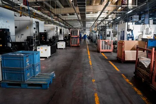
The conveyor topology changes which component the interlock is actually protecting. On a motorized roller conveyor, each roller card is a 24 VDC MDR that the operator can stall with a handshake grip, so the interlock's job is mainly to drop zero-pressure-accumulation release upstream and stop zone-to-zone hand-off [S4]. The contactor on the 120 VAC supply feeding the DC bus is the upstream permissive, and a single gate switch in series with that supply cuts the entire MDR run.
On a chain-driven live roller conveyor, power is transmitted from a central shaft via poly-V belts or roller chains to heavy rollers, with the whole drive train connected to an energy-efficient electric motor through the line shaft [S3]. Here the interlock must drop the contactor ahead of the gear motor, because the chain-and-sprocket path is the real nip hazard, not the roller surface. On a line-shaft conveyor, every roller is driven off one rotating shaft through small belt-and-spool connections, and the spool is itself a passive safety element: if clothing catches, the spool slips and that roller stops turning [S2]. A roller bearing failure on that shaft can lock the spool, so the interlock is still needed as a hardwired backup even though the spool provides mechanical slip.
Standards, ratings, and the dry-contact rule
Lift-gate conveyor OEMs call out the dry-contact rule explicitly: the interlock provides a dry contact signal when the conveyor is in the ready position, with no voltage sourced from the switch itself [S9]. That keeps the switch compatible with both 24 VDC PLC inputs and 120 VAC safety relay coils, and lets the same gate be reused on legacy contactor logic and modern STO drives. The interlock is also expected to be positive-break, so a welded contact cannot be masked by a returning spring, and the safety relay upstream is expected to meet a Cat. 3 / PLd or equivalent functional safety level.
For hazardous-area or washdown duty, the switch itself is typically IP67 or IP69K, and the field wiring is brought back through an IP67 I/O block so the conduit entry does not become a leak path. The Turck TBEN module is a representative example: it carries both the power and the safety I/O through one M12 connector, which simplifies retrofit on existing CDLR lines [S1]. Conveyor builders that ship pre-engineered gate modules also publish the E-stop and interlock wiring in the same drawing set, so the field installer only has to land one cable per gate rather than wire each contact from scratch.
Commissioning checks that actually catch bad interlocks
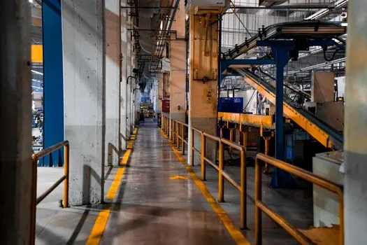
Three checks fail more bad interlocks than anything else. First, measure the drop-out time from gate-open to motor-decelerate: on a VFD with STO, this is typically well under 100 ms, and a stop category 0 (uncontrolled) drop will read several hundred ms. Second, force the gate switch open while the line is running a load, and confirm that the upstream zero-pressure-accumulation zones also release within one PLC scan, not just the local motor, because a single zone still running is how product piles into a stopped gate. Third, with the drive isolated, measure the interlock contact resistance cold and hot; a contact that reads 0.2 ohm cold and open-circuit hot is a welded or oxidized contact, and the safety relay will not detect it until the next gate cycle. [S2]
Mechanical checks matter just as much. On a hinged gate, the switch actuator must over-travel past the switch's positive-break point in the closed position, otherwise vibration will chatter the contact. On a latched gate, the interlock must be cam-operated or keyed, not a simple roller plunger, because a worker can defeat a roller plunger with a piece of tape. A road roller style pneumatic actuator is too soft for this duty; gate interlocks expect a hard, repeatable cam profile that the safety relay can trust. A gate that closes but does not re-seat the cam is exactly the failure mode that standard guard-door logic is designed to catch.
Limitations, failure modes, and what the interlock cannot do
A gate interlock only protects the gate it is mounted on, and only when wired into the upstream permit. Common failure modes in the field include: a jumpered contactor coil, a switch wired in parallel with the E-stop instead of in series, a safety relay with the reset button held down, and a gate that closes mechanically but does not re-engage the cam. Each of these defeats the interlock while leaving the conveyor fully runnable, and none of them is detectable from the HMI without an explicit contactor-auxiliary feedback check. [S2]
For higher-risk zones, the interlock is paired with a Cat. 4 / PLe guard door switch and a dedicated safety controller, not a general-purpose PLC, because a general-purpose PLC's enable output is not rated as a safety output. Conveyors that feed palletizers, robotic pallet discharge, or AGV handoffs typically require that level, while a manual pack-and-ship line can usually stop at Cat. 3 / PLd. Either way, the interlock's job is the same: it is a hardwired, positive-break, dry-contact gate in the run-permit chain, and the conveyor must not start, or must coast and drop, while that contact is open.
For readers sizing a new MDR line, two trackable signals are worth monitoring: the take-up of 24 VDC MDR over 480 V gear motor on greenfield conveyor projects, and the move toward safety-over-Ethernet protocols such as CIP Safety and PROFIsafe on TBEN-class I/O blocks, which collapses the gate interlock wiring into the same M12 trunk as the roller drive. Related reference on calculating belt conveyor TPH from belt width and speed is useful when the gate sits at a transfer between belt and roller sections, because the interlock timing has to match the heavier belt's stop distance, not the lighter roller's.