
A bar bender reads a BBS one row at a time, using each line as a complete cutting and bending instruction: bar mark, nominal diameter, shape code, cutting length in mm, and quantity [S3]. The schedule converts a structural reinforcement drawing into individual production quantities, so the operator on the rebar bender is working from a spreadsheet, not the drawing itself.
For a typical UK or Commonwealth job, the shape code column points to BS 8666:2020 geometry (00 for straight, 13, 21, 33, 41, 44, 51 etc. for standard bent shapes) and the A/B/C/D columns give the leg dimensions in mm [S2]. For Indian and Middle East projects the same column is governed by IS 2502 shape codes [S1]. The operator pins the mandrel and pin set to match the shape code, sets the angle stop, feeds the bar to the mark, and trips the machine.
The minimum column set a bender actually uses
A workable schedule on the shop floor needs at least six fields: bar mark, type and size (H10, H16, T12 etc. in BS notation, or Ø12, Ø16 etc. in metric), shape code, A/B/C/D dimensions in mm, cutting length per bar, and total quantity [S2][S3]. Bar mark is the unique identifier stamped on the bent piece so it can be matched back to the drawing during installation; identical marks mean identical geometry [S2].
Type and size sets the bar diameter the bender must select from the rack; mixing diameters is the single most common site error and the easiest one to catch if the operator reads left to right [S3]. Total quantity is the field used for production planning, not for bending one bar: a row reading 20 bars × 5,000 mm × 12 mm means 20 identical pieces, not one 100 m bar [S3]. On a PLC-controlled bender the cutting length and shape code are sometimes pushed directly from the BBS spreadsheet to the machine, removing the manual transcription step.
Shape codes, bend angles, and how the machine is set
BS 8666:2020 shape codes are the operator's primary reference: each numeric code defines a fixed geometry (hook length, bend angle, leg layout) and the A/B/C/D/E dimensions fill in the variable lengths [S2]. Common codes on a bending machine include 00 (straight, no bends), 13 (180° hook both ends), 21 (90° bend one end), 33 (90° bends both ends), 41 (135° stirrup), and 51 (cranked bar) [S2].
For each shape code, the bender sets the central mandrel pin (diameter must match the bar size, typically 4d for ≤Ø16 and 7d for larger bars to prevent inside-crack failure), the two or three bending pins, and the angle stop. The schedule's A dimension is the distance from the bar end to the first bend, B is between bends, and so on, all in mm [S2]. When a row shows a 135° stirrup with A = 800 mm, B = 400 mm, the operator sets the back stop at 800 mm, bends 135°, slides to 1,200 mm cumulative, bends the opposite 135°, then cuts.
Cutting length versus theoretical length: the bend deduction
The cutting length in the schedule is not the sum of A+B+C+D leg dimensions; it is the theoretical length minus bend deductions plus hook allowances [S1][S3]. For a 90° bend on mild steel, the standard deduction is 2d (two bar diameters); for 135° it is 3d; for 180° hooks the addition is 4d + 60 mm minimum hook length, though BS 8666:2020 specifies 4d minimum with no explicit 60 mm rule [S1].
Schedules that quote only leg lengths without a separate cutting length column are common on smaller jobs and force the bender to do the math on the floor; production-grade BBS exports from software like StruCAD or Tekla include the calculated cutting length directly [S3]. A typical worked example: a 3,500 mm × 16 mm bent bar with two 90° bends has a 32 mm total deduction, so cutting length = 3,500 mm + 0 mm (no deduction if legs already include bend zones) or 3,468 mm depending on whether the schedule lists overall or developed length [S1]. Operators who skip this step over-order bar stock by 2-3% across a job.
Reading the schedule against the drawing and the standard
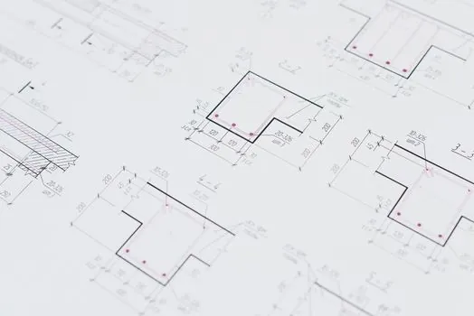
A BBS is a fabrication document, not a design document; the schedule should always be read together with the applicable structural drawing, the project specification, and the reinforcement standard (BS 8666:2020, IS 2502, or ACI 315) [S2][S3]. Discrepancies between BBS and drawing show up as mismatched bar marks, missing shape codes, or quantities that disagree with the bar count on plan; the bender should flag, not bend, when these appear.
For structural steel connection design or for contractors switching between standards, a useful habit is to verify the shape code against the bend angle listed: BS 8666 codes assume standard 90°, 135°, and 180° bends unless the schedule explicitly overrides with a non-standard angle [S2]. The weight columns in the BBS (kg/m and total kg) are derived from nominal mass per metre (0.888 kg/m for Ø12, 1.578 kg/m for Ø16, 2.466 kg/m for Ø20) and are used for procurement and delivery checks, not for bending setup [S3].
When the schedule format breaks down

Schedules that omit the shape code column, use non-standard leg dimensions, or list only overall length without bend details force the bender back to the drawing and add 5-10% to fabrication time [S2]. Schedules that mix metric and imperial units, or that use a proprietary shape-code system without a legend, are the most common cause of mis-bent deliveries on cross-border projects [S1].
Large infrastructure work, where one BBS row may cover 200+ identical bars, benefits from exporting the schedule directly into the bender's controller via CSV; manual transcription of 1,000-row schedules produces a measurable scrap-rate increase that drops back to near zero once the PLC imports the file directly. For process-engineering projects that involve embedded rebar in industrial valve actuator plinths or pressure transmitter equipment foundations, the same BBS workflow applies, but bar marks must be cross-referenced to the equipment anchor bolt plan, not just the civil drawing.
Track next: revision of BS 8666 and any IS 2502 update; wider adoption of CSV/Excel direct-to-bender workflows on mid-size commercial projects; and tighter integration between BBS exports and BIM reinforcement models for flow-meter and pumping-station concrete structures.
Background reading: Set a laser level's slope function for a drainage grade: procedure, math, and verification.