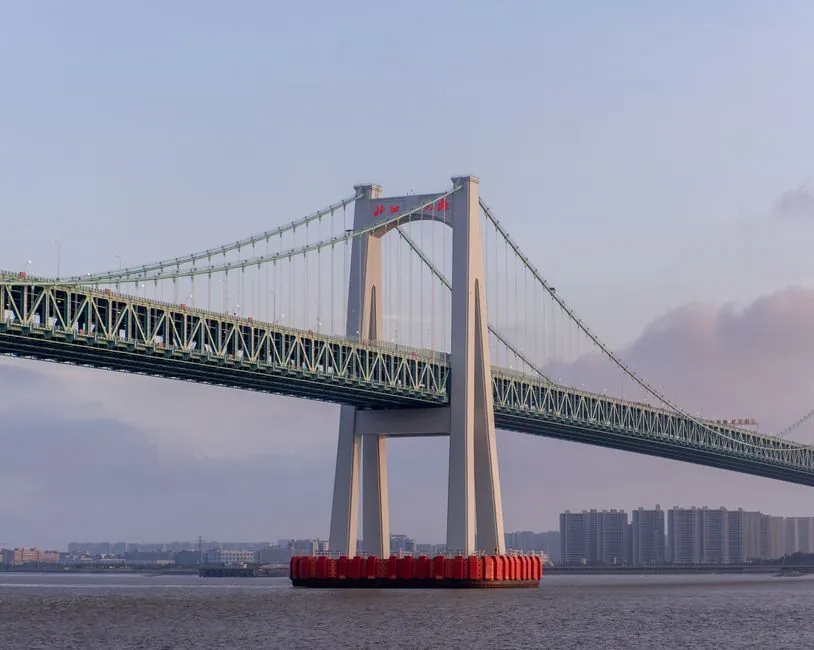
An underdeck suspended platform is a work cradle hung on wire ropes from the bridge structure above and rolled, craned, or carriage-mounted along the girder line as inspection or repair progresses [S1][S3].
Three principal travel modes are used in 2026 practice: a rope-and-hoist cradle that re-anchors span by span, a wheeled or tracked under-bridge access system (UBAS) carriage running on rails or directly on the girder flange, and a cantilever bracket that slides between fixed anchor points on the deck edge [S2][S3].
Three Travel Modes Compared: Cradle Step-Move, UBAS Carriage, and Cantilever Slide
An under-bridge access system travels along a bridge girder by one of three recognised methods, each with a different load path and disruption profile [S2].
The first method is the rope-and-hoist cradle: a modular galvanised deck driven by a matched pair of LTD-series hoists climbs or descends on wire ropes anchored to a deck-edge outrigger, counterweighted frame, pylon head, or temporary frame bolted to the deck [S3]. For along-girder travel the cradle is lowered, the upper anchorage is released, and the suspension is re-set on the next anchor point, so the platform effectively steps from span to span rather than rolling continuously [S3].
The second method uses a dedicated under-bridge access system, a wheeled or tracked carriage that grips the girder flange and runs along it, carrying the work platform below. The platform is suspended from the carriage, and the entire assembly translates horizontally as the carriage advances, which is the configuration that gives true continuous along-girder travel [S2].
The third method is the cantilever bracket: outrigger beams laid on the deck behind the barrier transfer load to the structure while the platform hangs from a slide rail on the outrigger, allowing the working deck to traverse short distances between fixed anchor points without releasing the main suspension [S3]. The choice between these three is governed by span length, girder geometry, traffic below, and the load capacity of the deck-edge anchorage [S2][S3].
Load Path and Suspension Hardware: Ropes, Hoists, and Girder Anchors
Bridge suspended platforms in current Indian specification use a standard capacity range of 500-1,000 kg, with the suspension hardware the same family as a building facade cradle: modular deck, matched pair of hoists, an independent safety rope with a centrifugal lock, and a control panel [S3].
The load path runs from the working deck up through the hoist wire ropes to the suspension beam, which in turn transfers the load to a deck-edge outrigger, a counterweighted parapet frame, or a temporary structure bolted to the deck [S3]. On a suspension bridge the equivalent vertical handoff is the 500 vertical suspender ropes spaced every 50 feet (15 m) along the Golden Gate deck, each transferring deck weight to the curving main cables above [S4]. The platform rigging mimics that logic on a smaller scale: the girder or deck above takes the role of the main cable, and the working platform is the deck hung beneath it [S1][S3][S4].
Engineered anchoring and load calculations are mandatory because the deck edge may have no slab to stand on, which is why bridge suspended platforms are quoted per drawing rather than off a catalogue [S3]. The WEB Deck modular suspended platform system is one example of a temporary work platform that replaces hanging scaffolding for underdeck areas and is rated for tidal immersion on Network Rail bridge projects [S5].
What the Underdeck System Is Suspended From: Outriggers, Counterweights, and Pylon Heads
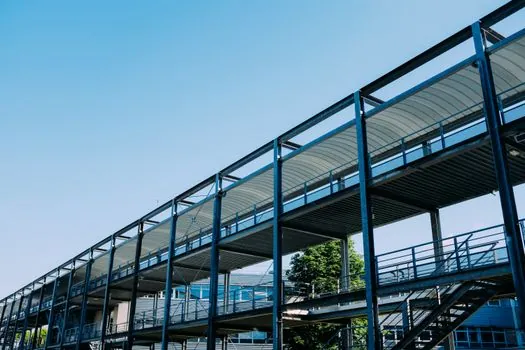
Because a bridge has no ground beneath the work area, the suspension has to be taken off the deck edge, off a crash barrier, off a temporary frame bolted to the deck, or off the pylon head, and the platform frequently has to work under a horizontal surface rather than beside a vertical one [S3].
A deck-edge outrigger with counterweight or tie-down is the most common anchorage on highway bridges; the outrigger beams sit on the deck behind the barrier, the counterweight resists overturning, and the platform hangs on dropper ropes from the outrigger nose [S3]. On cable-stayed and suspension bridges the same machine is re-rigged for three different jobs: stay-cable and anchorage inspection, pylon surface repair, and deck-soffit maintenance, each with its own rigging arrangement [S3].
The primary spanning members carrying the platform deck load across the distance between support points are typically wide-flange steel beams, lattice truss, or cable-supported structures, which are fundamentally different from the panel-frame and modular systems that dominate above-grade scaffold [S2]. The platform must span horizontally, often across a waterway, active roadway, or rail corridor, between support points that may be widely spaced bridge girders or abutment walls [S2].
Step-by-Step Travel Sequence: From Survey to Span-by-Span Repositioning
Before any platform travels, the bridge is surveyed to establish the span between available support points, the clearance between the underside of the deck and the surface below, the load capacity of the existing structural members at the proposed anchor locations, and the full horizontal extent of the work area [S2].
Once engineered, the platform's support system is matched to that envelope. The platform is then installed from the top of the structure and extended below the deck, eliminating the need for ground-based scaffolding and minimising disruption below [S1]. The platform's primary spanning members carry the platform deck load across the distance between support points, typically wide-flange steel beams, lattice truss, or cable-supported structures [S2].
To advance along the girder, the crew lowers the cradle, releases the upper anchorage, slides or rolls the suspension carriage to the next anchor station, re-attaches, and re-hoists. On a long viaduct the platform is repositioned span by span with the same crew and no dismantle-and-rebuild cycle, which is the productivity argument over full staging from barges or falsework towers [S3]. This is also why a suspended platform is typically the access method of choice where ground access is restricted to a river, a rail corridor, or an active highway [S3].
Selection Criteria: Span, Capacity, Traffic, and Environment
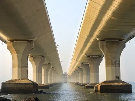
Selection between a cradle step-move, a UBAS carriage, and a cantilever slide is driven by four measurable criteria: span length, payload requirement, traffic state below, and environmental load [S2][S3].
Span length determines whether a single anchor station can cover the work zone or whether a wheeled carriage that runs continuously along the girder is required. Payload drives hoist size: standard capacities run 500-1,000 kg for straight ZLP cradles, while L-type and special-purpose builds handle pier heads, haunches, and cable geometry a facade cradle cannot [S3]. Traffic below dictates whether the platform must reach the soffit from above without obstructing the waterway or the road, which is the main reason suspended platforms win over full staging on river crossings [S3]. Environmental load covers wind, tide, and corrosion: the WEB Deck platform on the Network Rail bridge is designed to be submerged twice daily by high tides [S5].
Inspection cycle is set in India by IRC:SP:35 for bridges generally and IRC:SP:136-2023 for stay-cable bridges, and those cycles create the recurring demand for access equipment [S3]. The same engineer's reference also notes that on a bridge, the rigging is the engineering; the cradle is the easy part, and counterweight, anchorage, and wind assessment must be designed for that specific span rather than copied from a building job [S3].
Limitations and Failure Modes: Why the Rigging Drives the Design
Bridge suspended platforms inherit the working-at-height hazards of facade cradles and add span-specific risks: inadequate deck-edge load capacity, wind on an exposed soffit, and tidal or traffic impact on the anchor zone [S3][S5].
Where the deck edge cannot carry the suspension load, a ground-bearing scaffold rising from the banks of a waterway or a UBAS carriage that transfers load directly into the girder is preferred over a rope-hung cradle [S2]. Where the work area is too large to cover with a series of individually repositioned lifts, a fixed large-area platform that covers the full work zone in one installation is generally the most productive and often the safest solution, and this is the same logic that drives the use of a suspended ceiling-style spanning approach on industrial mezzanines and process platforms [S2].
Underdeck suspended platforms are not the right tool where the structure above cannot take the platform loads, where the work area is small enough for a rolling scaffold, or where the below-deck environment is open ground rather than water, road, or rail [S1][S2]. For typical underdeck access on bridges and elevated highways, however, a single girder crane-style philosophy of one primary beam carrying the platform across the span dominates the engineering, and the platform trolley concept of a wheeled carrier that grips the girder flange and runs along it is the closest analogue to a UBAS carriage used on a building [S2].
Standards, Sourcing, and Sizing References
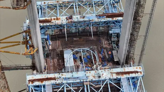
Under-bridge platforms in 2026 practice are referenced to bridge inspection standards rather than generic scaffold codes: IRC:SP:35 for general bridges and IRC:SP:136-2023 for stay-cable bridges, with the engineering envelope set by span survey, deck-edge capacity, and environmental load rather than by a catalogue number [S3].
Sourcing in the United States is via specialist vendors who supply and install under-bridge and large-area platform systems, with comparison criteria including spanning capability, load rating, and availability for the project window [S2]. Through Scaffold Exchange, buyers can find vendors across the U.S. who supply and install under bridge and large area platform systems and compare their spanning capabilities, load ratings, and availability for the project [S2]. Globally, suppliers such as WEB Systems International publish modular suspended platform systems explicitly rated as a replacement for hanging scaffolding on underdeck areas, including the WEB Deck rigid platform system and tension netting for atypical geometries [S1][S5].
Trackable signals for the next procurement cycle include any revision of the IRC:SP:35 and IRC:SP:136-2023 inspection intervals, broader UBAS carriage deployment on highway viaducts, and continued migration from hanging scaffolding to modular suspended decks such as the WEB Deck on tidal and over-water bridges [S3][S5]. A platform scale-style load check at each new anchor station remains the practical field safeguard, and an overhead bridge crane-style pre-move walk-down of the suspension path is the closest transferable habit from factory practice to bridge site work [S2][S3].
Background reading: Forklift Class I to VII: power source, tires, and where each applies.