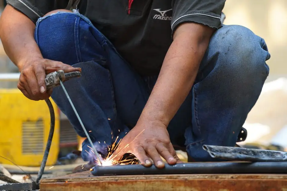
Arc welding strikes and holds a weld pool by forcing current across a sustained gap between an electrode and the base metal, where a constant-current power supply keeps amperage roughly steady as arc length drifts, so the arc stays lit through normal hand movement [S2][S4].
For shielded metal arc welding (stick), the open-circuit voltage of the supply is typically in the 20 V range once an arc is established, and the operator sets current on the machine to match rod diameter and joint thickness, with a 2.5 mm E6013-class rod commonly run near 100 A in field practice [S3][S4].
The Strike: Closing the Circuit Across a Gap
Striking the arc is the act of closing an electrical circuit between electrode and workpiece in a controlled way. In stick welding, the welder taps or scratches the flux-coated electrode against the base metal and then quickly retracts it 2–4 mm to set a stable arc gap; in TIG, the tungsten is usually touched to the pool under HF or lift-arc start assist, then lifted to establish the arc without contaminating the electrode [S1][S2].
The physical event is a breakdown of the air gap: as the electrode approaches the workpiece, the electric field ionizes the air, current flows, and a sustained plasma column forms. The arc column reaches roughly 6,500 °F at the work face, enough to melt steel and the consumable electrode together [S5]. A welder who repeatedly sticks the rod is running too little current for the rod size, a common field failure at 60 A on a 2 mm E6013, where bumping to 80–100 A clears it up [S3].
Maintaining the Arc: Constant-Current vs Constant-Voltage
Once struck, the arc is held by a power source whose output curve matches the process. Constant-current (CC) supplies are used for manual processes, stick (SMAW) and TIG (GTAW), because they hold amperage nearly flat as voltage (i.e. arc length) wanders, so a trembling hand does not collapse the arc [S4].
Constant-voltage (CV) supplies do the opposite and are paired with wire processes: MIG/GMAW, flux-cored (FCAW), and submerged arc (SAW). In CV mode, if the wire tip drifts toward the plate, current spikes and burns the wire back to its set stickout, which is why wire welding tolerates small distance changes without extinguishing [S4]. Under normal stick arc length, a CC supply sits near 20 V across the gap, and current is set by the operator via the amperage knob or tap switch on the machine [S4].
Polarity, Current Type, and Heat Balance
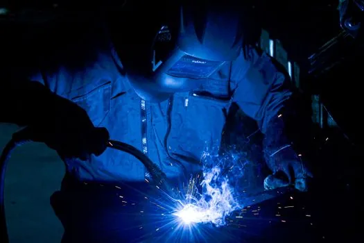
Arc welding power supplies deliver either direct current (DC) or alternating current (AC), and polarity drives where the heat lands. The anode side of the arc carries roughly 60% of the heat, so reversing polarity shifts penetration and bead profile without changing the amp setting [S4]. For stick welding, DC+ (electrode positive) is the most common polarity, giving deeper penetration and a tighter bead, while DC- (electrode negative) shifts more heat into the workpiece and is used for thin material or hardfacing overlays [S4][S5].
AC is used where the magnetic arc blow of DC becomes a problem, notably in TIG welding of aluminum, where the natural rectification effect of an oxide-coated surface would otherwise extinguish a DC arc; the AC cycle cleans the oxide on the positive half and penetrates on the negative half [S5]. The practical upshot: a machine rated for AC/DC output covers aluminum and stainless without a second power source, while a DC-only stick welder is enough for most field steel work.
Consumable vs Non-Consumable Electrode Paths
The same arc physics serves two very different electrode strategies. Consumable-electrode processes, stick (SMAW), MIG (GMAW), and flux-cored (FCAW), feed or coat a filler metal that melts into the pool; the shielding job is done either by a flux coating that becomes slag, by an external inert or active gas (argon, argon/CO2 mixes), or by a self-shielding flux core that decomposes to its own protective atmosphere [S4][S5].
Non-consumable processes keep a tungsten electrode (GTAW/TIG) intact and add filler rod by hand if needed, with an inert argon shield protecting both the tungsten and the pool. Comparing the two on common selection criteria: stick scores on portability and outdoor tolerance to wind, MIG/GMAW scores on speed and clean bead on steel, flux-cored bridges outdoor productivity on thick structural steel, and TIG scores on precision and exotic alloys at the cost of slower deposition. A useful cross-reference for the broader welding and cutting tool category is the welding and cutting tool reference page, which maps these process families to the equipment that drives them.
Open-Circuit Voltage, Duty Cycle, and Why the Arc Stays Lit

The arc stays lit because the power source holds either current (CC) or voltage (CV) at a stable setpoint faster than the welder can move the electrode. During the actual weld, the machine drops from open-circuit voltage (OCV), often 50–80 V on a stick machine, down to the loaded arc voltage near 20 V once current flows, and the difference is what the machine's internal inductor or inverter regulates against [S4].
Duty cycle is the time share a machine can deliver its rated output in a 10-minute window without tripping thermal protection; a 200 A at 60% duty stick welder, for example, can sustain 200 A for 6 of every 10 minutes before the thermostat opens. Inverter-based machines strike more easily than older transformer sets because their electronic control forces a clean current ramp the instant contact is made, which is why hobbyists moving from a transformer to an inverter notice the difference on the first rod [S3]. The construction-machinery ecosystem that depends on these processes, from boom-mounted welders to pipe-laying spreads, is catalogued in the construction machinery and equipment reference.
Common Failure Modes When the Arc Will Not Hold
Four field conditions account for most "arc won't hold" complaints. First, undersized amperage for rod diameter, which welders can self-diagnose by simply turning the amp knob up 20–30 A and re-striking [S3]. Second, contaminated or damp flux coatings, especially on cheap E6013 rods, which is why rod quivers and ovens are standard on structural sites. Third, poor work clamp connection, where paint, rust, or an oxidized ground path forces the supply to compensate and chokes the arc. Fourth, mismatched process to supply, running a stick rod on a CV wire-feeder power source or vice versa, since the output curve is wrong for the arc-length behaviour the process needs [S4].
When the problem is the process not the machine, the fix is procedural rather than electrical: clean the metal, dry the rod, verify clamp bite, and confirm CC vs CV mode on the front panel. For deeper process-side guidance, including parameter sheets and pitfall lists that apply to similar stud and stick workflows, see the stud welding parameter qualification reference and the stud welding in vertical and overhead positions field note, which use the same current, time, and polarity framework as stick arc control.
Trackable signals to watch over the next quarter: inverter-based multi-process machines replacing legacy transformer-only stick welders in fabrication shops; higher OCV (80 V and above) on entry-level inverter stick units to improve scratch-start on cellulosic E6010/E7018 rods; and wider adoption of AC/DC TIG modules as standard rather than optional, reflecting aluminum work migrating from specialist shops to general fabrication. The base encyclopedia entry for the equipment family is at the arc welder reference page, which consolidates the process taxonomy, current type, and electrode categories covered above.