
Under IEC 60034-11:2020, built-in thermal protection places a temperature sensor (PTC thermistor, Pt100/RTD, or PTC triplet) inside the stator winding and trips on actual hotspot temperature, while an external thermal overload relay sits in the motor starter and infers heating from line current against a bimetallic or electronic model [S3][S1].
IEC 60034-11:2020 (Edition 3.0, published 2020-10) defines the protection codes engineers still quote today: TP 111 for slow overload only, TP 112 for slow overload + locked rotor, TP 121 for slow overload + rapid re-load, TP 122 for the most demanding duty (slow overload + locked rotor + rapid re-load), and TP 211 for a single PTC at one specified trip temperature [S3]. For locked-rotor survival the standard requires either the motor's thermal mass to ride through TP 111 within the t6 time, or the additional sensor / trip class called out by TP 112/121/122 [S1][S3].
What each device actually measures
An external thermal overload relay measures the three line currents entering the starter, integrates a thermal model (bimetallic strip, eutectic alloy, or electronic I²t), and trips the contactor. It does not see rotor temperature, cooling-air temperature, or whether the motor is running on a VFD with reduced self-cooling [S6][S5]. A thermal protector built into the motor per IEC 60034-11 measures the actual winding hotspot, which is the failure point the user actually cares about [S1][S3].
Because the relay cannot read the winding, NEC 430.32 requires it to be sized at no more than 125% of the motor nameplate full-load current for continuous-duty motors with a 1.15 service factor (or 115% for 1.0 SF motors) [S8]. IEC 60034-11 itself warns that "a current overload relay does not normally provide protection against repeated rapid overload variations," which is the exact use case for which the built-in PTC/RTD path exists [S3].
Decision matrix: four criteria, two options
Engineers selecting between these options generally weigh four criteria. Sensing source: external relay reads current only; built-in reads stator temperature directly [S6][S3]. VFD compatibility: external relay drifts when the drive reduces voltage/harmonics at low speed and self-cooling drops; built-in PTC/RTD sees the real hotspot, which is why VFD-driven motors almost always ship with a thermistor pair in the winding [S5]. Code acceptance: NEC 430.32(A)(1) accepts a separate overload device, 430.32(A)(2) accepts a thermal protector integral with the motor, and 430.32(A)(3) accepts a protective device integral with the motor, so any of the three paths is code-compliant for general-purpose motors in the US [S5]. Short-circuit coverage: a thermal overload relay is not a short-circuit device and must be paired with fuses or a motor protection circuit breaker (MPCB) per IEC 60947-4-1, while a thermistor relay similarly needs upstream short-circuit protection [S4][S2].
For a fix-speed, standard induction motor on a clean sinusoidal supply, an external thermal overload relay (Class 10 or Class 20) sized at 115–125% FLA is usually enough, and it costs less than rewiring the motor with a smart thermistor module [S8][S4]. For a VFD, a servo, a high-inertia load (flywheel, large fan, crusher), or any application with frequent start-stop cycles, the built-in IEC 60034-11 sensor should be added, and a separate overload relay is not a substitute for it [S5][S3].
Use cases and the failure modes engineers actually hit
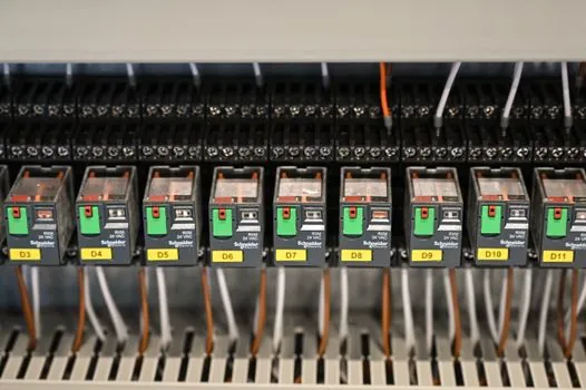
Locked-rotor at start is the classic failure mode where current-based protection alone undersizes. A standard TP 111 motor with only a slow-overload sensor can survive locked-rotor only if the locked-rotor withstand time exceeds the actual stall time, which is why IEC 60034-11 forces the TP 112/121/122 codes whenever stall survival cannot be guaranteed by thermal mass alone [S1][S3]. In practice, that means a separate locked-rotor sensor or a higher TP class in the winding, with the trip relay interpreting the PTC triplet externally.
VFD-driven motors present a second failure mode the external relay cannot see. The fan-cooled TEFC motor loses about 50–70% of its cooling airflow when run below roughly 30–50% of base speed, so the winding runs hotter than the current suggests; the only way to catch that is a built-in PTC or Pt100 in the stator, paired with a trip relay set to the sensor's rated trip temperature (commonly 130 °C, 150 °C, or 170 °C for Class B/F/H insulation) [S5][S3].
Cable protection is a third, often-overlooked limitation. A thermistor relay embedded in the motor only sees the motor's hotspot, not the supply cable between the starter and the motor terminal box, so the cable still needs an upstream overload device sized per NEC 430.32 or its IEC equivalent [S2]. For motor protection relay coordination in a switchgear lineup, see the protection relay and motor protection relay reference pages for the device families that sit one tier above the starter.
Standards, codes, and how to spec it without getting burned
IEC 60034-11:2020 is the governing standard for the built-in sensor side, covering both the thermal protector itself and the assignment of TP codes by duty cycle [S3]. For the external side, IEC 60947-4-1 covers motor protection circuit breakers and the combination-starter ratings used in EU panels, while NEC 430.32 in the US sets the 115–125% FLA sizing rule and the (A)(1)/(A)(2)/(A)(3) three-path acceptance [S8][S4][S5]. The two systems are not interchangeable in wording, but both accept the "separate overload device + built-in thermal sensor" combination as the most defensive spec for industrial motors [S2][S8].
For thermal-measurement-based protections in a wider switchgear context, a thermal relay handles the bimetallic/eutectic overload class, while a microcomputer-based protection unit covers the multi-function numerical relays that combine overload, phase loss, earth-fault, and PTC thermistor input in one device. In fire- or hazardous-area installations where the relay itself must survive heat, thermal waterproofing practices for the enclosure also feed back into the relay selection.
Recommended spec pattern for a 2026 industrial motor
For general-purpose TEFC or ODP induction motors on a fixed supply: specify an external thermal overload relay (Class 10 trip for normal start, Class 20 for high inertia) sized at 115–125% of nameplate FLA, and request a built-in IEC 60034-11 PTC triplet (typically 150 °C or 170 °C rated) as a backup wired to a thermistor trip relay, even where the local code does not strictly require it [S8][S3][S1].
For VFD-driven or servo-driven motors: make the built-in PTC or Pt100 mandatory in the winding, and use the external overload relay purely as cable and short-circuit coordination. For high-inertia loads (large centrifuges, crushers, mixers), upgrade the TP code from TP 111 to TP 112 or TP 121/122 so the locked-rotor envelope is covered, and verify that the drive's stall-time limit does not exceed the motor's t6 time from the manufacturer's data sheet [S1][S3]. For related motor-control engineering reading, see AC torque motor output torque vs supply voltage: how adjustment actually works.