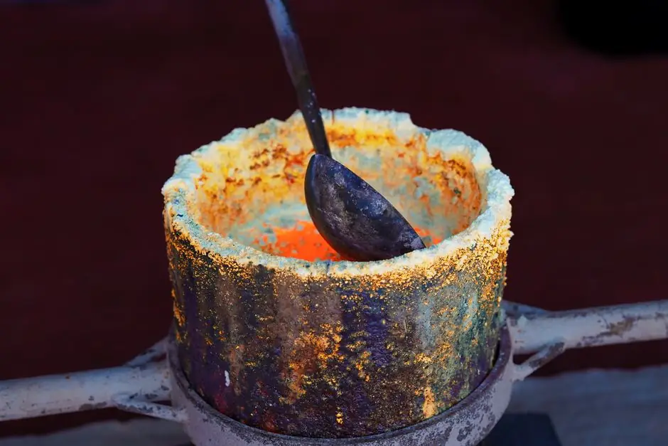
In a crucible furnace the heat source changes everything downstream: melt time, metal loss, atmosphere control, and the wear parts the maintenance team stocks. Induction crucible furnaces use an alternating-current copper coil to drive eddy currents in the conductive charge, while resistance crucible furnaces push current through resistance wires or rods that then radiate and conduct heat into the crucible wall [S1][S2][S7].
That single difference in heat path dictates nearly every specification downstream: coil frequency versus element material, refractory geometry, melt-rate in kilograms per hour, and even the type of crucible the foundry stocks. The comparison below is built around the mechanism, not the brand, with a decision matrix for shops weighing a new build versus a retrofit.
Direct induction heating: eddy-current path inside the charge
In an induction crucible furnace, an AC current in a surrounding copper coil produces a time-varying magnetic field that penetrates a non-conductive crucible and induces circular eddy currents directly in the molten or solid metal charge; the charge's own electrical resistance (I²R loss) is what generates the heat [S2][S4][S7]. Practical build sizes on the market range from laboratory 1–2 kg gold units through mid-range 10–250 kg hydraulic-tilt production furnaces used in jewellery and copper-alloy casting [S1].
Because the magnetic field passes through an insulating crucible, the crucible itself stays comparatively cool, while the melt receives heat from the inside out, and the Lorentz force on the induced currents also produces a built-in electromagnetic stirring action that homogenises the bath [S3][S4]. The melting surface reference page covers this equipment class in more detail at the crucible furnace entry, and the underlying coil assembly used to drive the field is documented on the induction furnace page.
Indirect resistance heating: element-to-crucible radiation path
Resistance crucible furnaces generate thermal energy by passing current through resistive heating elements, typically metallic wires, FeCrAl rods, silicon carbide, or molybdenum disilicide, wound around or stacked against the outside of an alumina or clay-graphite crucible; the element heats first and then transfers that energy to the crucible by conduction and radiation, after which the crucible finally transfers heat to the charge [S3][S4]. This is the same indirect chain used in muffle and box furnaces adapted to a crucible geometry.
The advantage is mechanical simplicity and the ability to push above 1,500 °C with appropriate element selection, which makes resistance designs common in ceramics, glass, and small-scale precious-metal work where the charge is non-conductive or where extreme temperatures are needed without the complications of high-frequency power [S3]. The penalty is a longer, multi-step energy path: electricity → element → crucible wall → charge, which slows ramp rates and accumulates heat losses at every interface.
Side-by-side decision matrix: induction vs resistance crucible furnaces
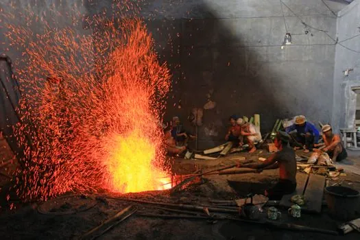
The most useful way to read the mechanism gap is as a decision matrix on four criteria that procurement, process, and maintenance all care about [S3][S6]:
Melting speed and energy efficiency. Induction heats the charge directly, so the reported trend is faster melt cycles with lower energy waste; resistance designs are slower to reach and sustain melting temperatures and are described as less energy efficient in head-to-head comparisons [S3]. For a 100 kg copper charge this typically shows up as a roughly 30–50% shorter cycle on a medium-frequency induction unit, although exact deltas depend on frequency, insulation, and charge geometry.
Capacity and load profile. Resistance crucible furnaces are well matched to small and medium loads, including small-scale or precious-metal melts; induction units scale more cleanly from kilograms into tens of tonnes and are standard in copper-alloy and steel foundry operations [S1][S3][S5].
Process quality. Induction delivers electromagnetic stirring that gives a homogeneous bath and lower oxidation losses, but the input charge must already be clean and well characterised because induction refining is limited; resistance furnaces handle a wider range of charge chemistries but expose the melt to higher oxidation risk through the longer hot-path [S3][S4].
Maintenance and consumables. Resistance heating elements wear out and require periodic replacement, while an induction system has no fragile heating element but does require coil cooling, capacitor-bank servicing, and (on IGBT sets) periodic stack checks [S3]. Choosing between them is therefore a tradeoff between element-replacement downtime and power-electronics upkeep, a tradeoff that also shows up in linear-motion hardware selection as described in the linear stepper motor spec map.
Crucible material and configuration: what each mechanism forces
The heating mechanism dictates the crucible specification rather than the other way around. In an inductive setup the crucible is a ceramic (alumina, quartz, or similar) chosen specifically because it is electrically insulating and magnetically transparent, so the coil's field passes straight through the wall and the eddy currents form inside the charge; the outside of the coil is then protected by dense refractory-brick housing that supplies thermal insulation and physical shielding [S4].
In a resistance setup the crucible is usually alumina or clay-graphite and the resistive wire is wound directly around the outside; insulation is typically lighter alumina-fibre cotton whose only job is to trap radiant heat from the hot element-crucible assembly [S4]. Indirect heating therefore tends toward a simpler refractory package but accepts a slower, multi-step energy transfer. The contrast in eddy-current physics is laid out on the solenoid coil reference page, which describes the same field-coupling behaviour used in these furnaces.
Use-case routing: which mechanism fits which job
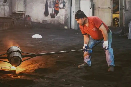
For foundries running ferrous or non-ferrous melts in the 10–250 kg range with tight temperature windows and high uptime expectations, induction crucible furnaces are the default choice: faster cycle, electromagnetic stirring, and clean atmospheres dominate the economics, and standard build sizes from jewellery-scale units up to 250 kg hydraulic-tilt production furnaces are widely available [S1]. For aluminium-ingot supply-chain nodes, the same induction advantage drives selection; the aluminium ingot vs billet vs slab comparison walks through how the upstream melt choice shapes downstream forging stock.
For laboratories, ceramics, glass, and small precious-metal work where the charge may be non-conductive, where peak temperatures above 1,500 °C matter more than melt rate, or where capital cost dominates the decision, resistance crucible furnaces remain the pragmatic fit [S3]. Crucible selection (clay-graphite for general foundry work, alumina for higher-purity or resistance-heated systems) is the secondary decision that follows once the mechanism is fixed. When the process involves vacuum or controlled-atmosphere melting, both mechanisms can be packaged inside a vacuum chamber, and the choice between them is governed mainly by charge conductivity and required ramp rate [S5].
Selection criteria and watch-outs for the spec sheet
When the comparison moves to a written specification, four numbers carry the decision: maximum operating temperature, melt rate in kilograms per hour, specific energy consumption in kWh per tonne, and the duty cycle of the heating element or coil [S3][S6]. For induction, add coil frequency (typically 1 kHz to 100 kHz for crucible sizes in this class) and power factor; for resistance, add element material grade, maximum surface watt loading, and expected element life in hours.
The limits of each mechanism are worth flagging before purchase. Induction cannot refine a charge, so the input must be clean and well characterised, and certain alloying elements may oxidise and need re-addition after the melt [S3]. Resistance elements degrade with thermal cycling and oxidise at high temperature, which is the dominant maintenance line item and the reason element-replacement intervals appear on every vendor's preventive-maintenance list. A common pitfall in retrofit projects is matching a resistance element's maximum watt density to a different crucible diameter, which creates hot spots and premature element failure; an equally common pitfall in induction retrofits is undersizing the cooling-water circuit for the new coil, which trips thermal cutouts and derates the furnace. For shops running mixed-foundry work, the coreless vs channel induction decision map is a useful complement, since the coreless channel pair is the dominant topology for crucible-style induction units.
Standards, sourcing, and the verifiable next signals to track
Standard references for this equipment class include the IEC 60079 series for hazardous-area electrical equipment around molten metal, ATEX 2014/34/EU for European explosive-atmosphere certification, and NEMA / IP ratings for cooling-water and dust ingress on the coil and power-cabinet enclosures. For foundries shipping cast product into oil-and-gas or pressure-containing service, downstream standards such as NACE MR0175 for sour-service alloys and ASME B16.34 for valve bodies also govern the resulting melt specification, although they do not directly select the furnace type. [S1]
Trackable signals through the rest of 2026 include any further consolidation of medium-frequency IGBT power supplies for the 50–500 kW crucible-furnace class, any published efficiency-delta benchmarks between silicon-carbide and molybdenum-disilicide resistance elements, and any movement on grid-side demand-response rebates that change the operating-cost math for high-power induction units. Sourcing for new builds should also weigh local availability of spare crucibles and elements, because the dominant cost of ownership on a resistance crucible furnace is consumable element replacement, and on an induction crucible furnace it is coil and capacitor-bank service.